OVFL OVFL
T1CC0
0000h
T0310-01
www.ti.com
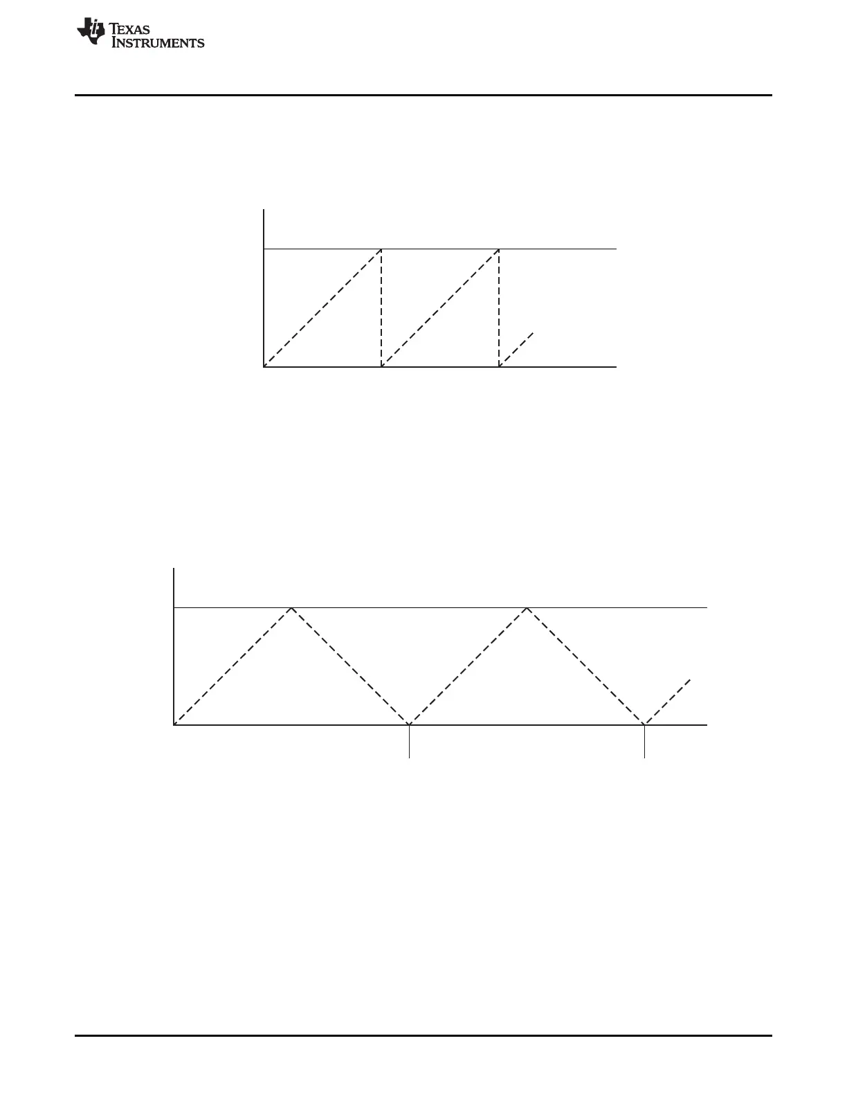
Up/Down Mode
value above T1CC0, the interrupt flag T1STAT.OVFIF is set when the terminal count value (0xFFFF) is
reached, after which the counter wraps to 0x0000. An interrupt request is generated if enabled, see
Section 9.10 for details. If a periodic interrupt is wanted at the period value, this can be obtained by
enabling an output compare interrupt on channel 0, as explained in Section 9.8. The modulo mode can be
used for applications where a period other then 0xFFFF is required. The counter operation is shown in
Figure 9-2.
Figure 9-2. Modulo Mode
9.5 Up/Down Mode
In the up/down timer mode, the counter repeatedly starts from 0x0000 and counts up until the value held
in T1CC0H:T1CC0L is reached, and then the counter counts down until 0x0000 is reached, as shown in
Figure 9-3. This timer mode is used when symmetrical output pulses are required with a period other than
0xFFFF, and therefore allows implementation of center-aligned PWM output applications. The interrupt
flag T1STAT.OVFIF is set when the counter value reaches 0x0000 in the up/down mode. An interrupt
request is generated if enabled, see Section 9.10 for details..
Figure 9-3. Up/Down Mode
9.6 Channel-Mode Control
The channel mode is set for each channel with its control and status register, T1CCTLn. The settings
include input capture and output compare modes.
9.7 Input Capture Mode
When a channel is configured as an input capture channel, the I/O pin associated with that channel is
configured as an input. After the timer has been started, a rising edge, falling edge, or any edge on the
input pin triggers a capture of the 16-bit counter contents into the associated capture register. Thus, the
timer is able to capture the time when an external event takes place.
109
SWRU191C–April 2009–Revised January 2012 Timer 1 (16-Bit Timer)
Submit Documentation Feedback
Copyright © 2009–2012, Texas Instruments Incorporated
 Loading...


