I
Q
250 kbps
62. 5 ksymbol/s
2 Mchips/s 1Mchips/s
1Mchips/s
Transmitted
Bit-Stream
(LSBFirst)
Modulated
Signal
( toDACs)
Bit-to-
Symbol
Symbol-
to-Chip
O-QPSK
Modulator
B0306-01
t
C
2t
C
I-Phase
Q-Phase
1
1 1 1 1 1 1 11
1 1 1 1 1 1 1
0 0 0 0 0 0 0 0
0 0 0 0 0 0 00
M0107-01
www.ti.com
IEEE 802.15.4-2006 Modulation Format
Figure 23-1. Modulation
Table 23-2. IEEE 802.15.4-2006 Symbol-to-Chip Mapping
Symbol Chip Sequence (C0, C1, C2, … , C31)
0 1 1 0 1 1 0 0 1 1 1 0 0 0 0 1 1 0 1 0 1 0 0 1 0 0 0 1 0 1 1 1 0
1 1 1 1 0 1 1 0 1 1 0 0 1 1 1 0 0 0 0 1 1 0 1 0 1 0 0 1 0 0 0 1 0
2 0 0 1 0 1 1 1 0 1 1 0 1 1 0 0 1 1 1 0 0 0 0 1 1 0 1 0 1 0 0 1 0
3 0 0 1 0 0 0 1 0 1 1 1 0 1 1 0 1 1 0 0 1 1 1 0 0 0 0 1 1 0 1 0 1
4 0 1 0 1 0 0 1 0 0 0 1 0 1 1 1 0 1 1 0 1 1 0 0 1 1 1 0 0 0 0 1 1
5 0 0 1 1 0 1 0 1 0 0 1 0 0 0 1 0 1 1 1 0 1 1 0 1 1 0 0 1 1 1 0 0
6 1 1 0 0 0 0 1 1 0 1 0 1 0 0 1 0 0 0 1 0 1 1 1 0 1 1 0 1 1 0 0 1
7 1 0 0 1 1 1 0 0 0 0 1 1 0 1 0 1 0 0 1 0 0 0 1 0 1 1 1 0 1 1 0 1
8 1 0 0 0 1 1 0 0 1 0 0 1 0 1 1 0 0 0 0 0 0 1 1 1 0 1 1 1 1 0 1 1
9 1 0 1 1 1 0 0 0 1 1 0 0 1 0 0 1 0 1 1 0 0 0 0 0 0 1 1 1 0 1 1 1
10 0 1 1 1 1 0 1 1 1 0 0 0 1 1 0 0 1 0 0 1 0 1 1 0 0 0 0 0 0 1 1 1
11 0 1 1 1 0 1 1 1 1 0 1 1 1 0 0 0 1 1 0 0 1 0 0 1 0 1 1 0 0 0 0 0
12 0 0 0 0 0 1 1 1 0 1 1 1 1 0 1 1 1 0 0 0 1 1 0 0 1 0 0 1 0 1 1 0
13 0 1 1 0 0 0 0 0 0 1 1 1 0 1 1 1 1 0 1 1 1 0 0 0 1 1 0 0 1 0 0 1
14 1 0 0 1 0 1 1 0 0 0 0 0 0 1 1 1 0 1 1 1 1 0 1 1 1 0 0 0 1 1 0 0
15 1 1 0 0 1 0 0 1 0 1 1 0 0 0 0 0 0 1 1 1 0 1 1 1 1 0 1 1 1 0 0 0
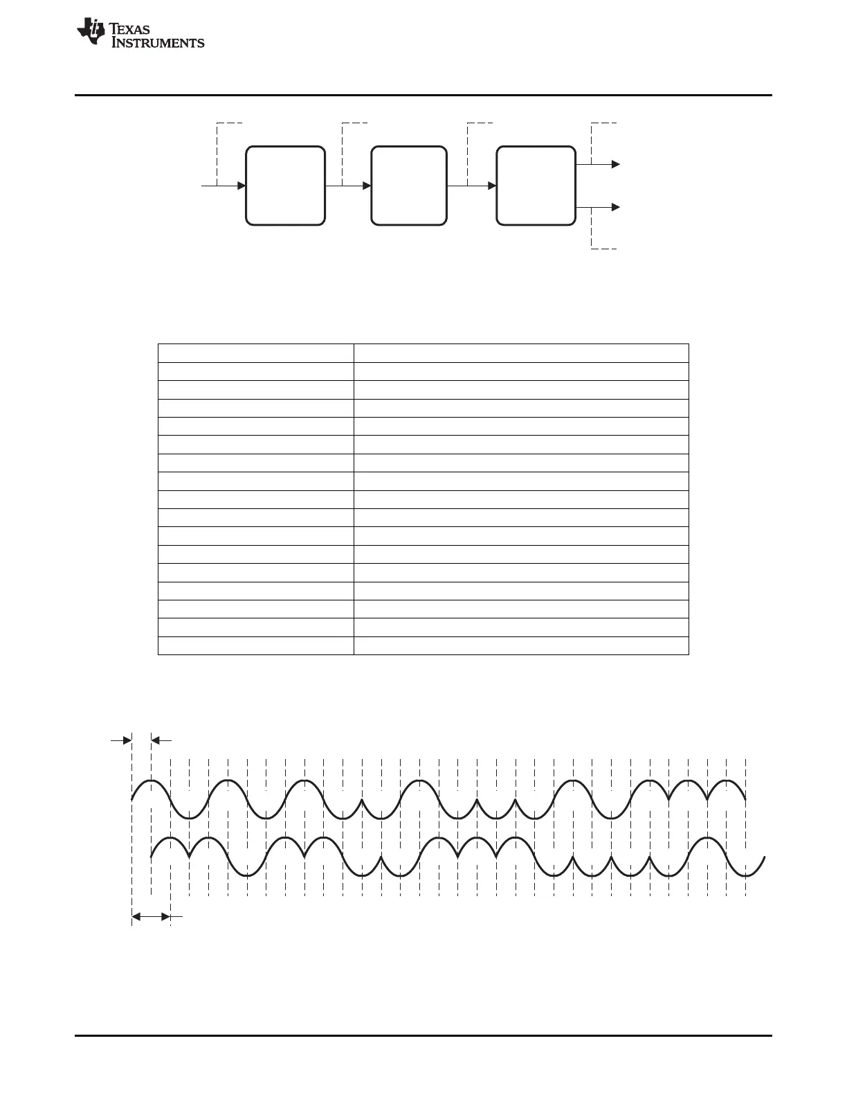
The modulation format is offset – quadrature phase shift keying (O-QPSK) with half-sine chip shaping.
This is equivalent to MSK modulation. Each chip is shaped as a half-sine, transmitted alternately in the I
and Q channels with one-half chip-period offset. This is illustrated for the zero-symbol in Figure 23-2.
Figure 23-2. I/Q Phases When Transmitting a Zero-Symbol Chip Sequence, t
C
= 0.5 μs
227
SWRU191C–April 2009–Revised January 2012 CC253x Radio
Submit Documentation Feedback
Copyright © 2009–2012, Texas Instruments Incorporated
 Loading...


