www.ti.com
USART Flushing
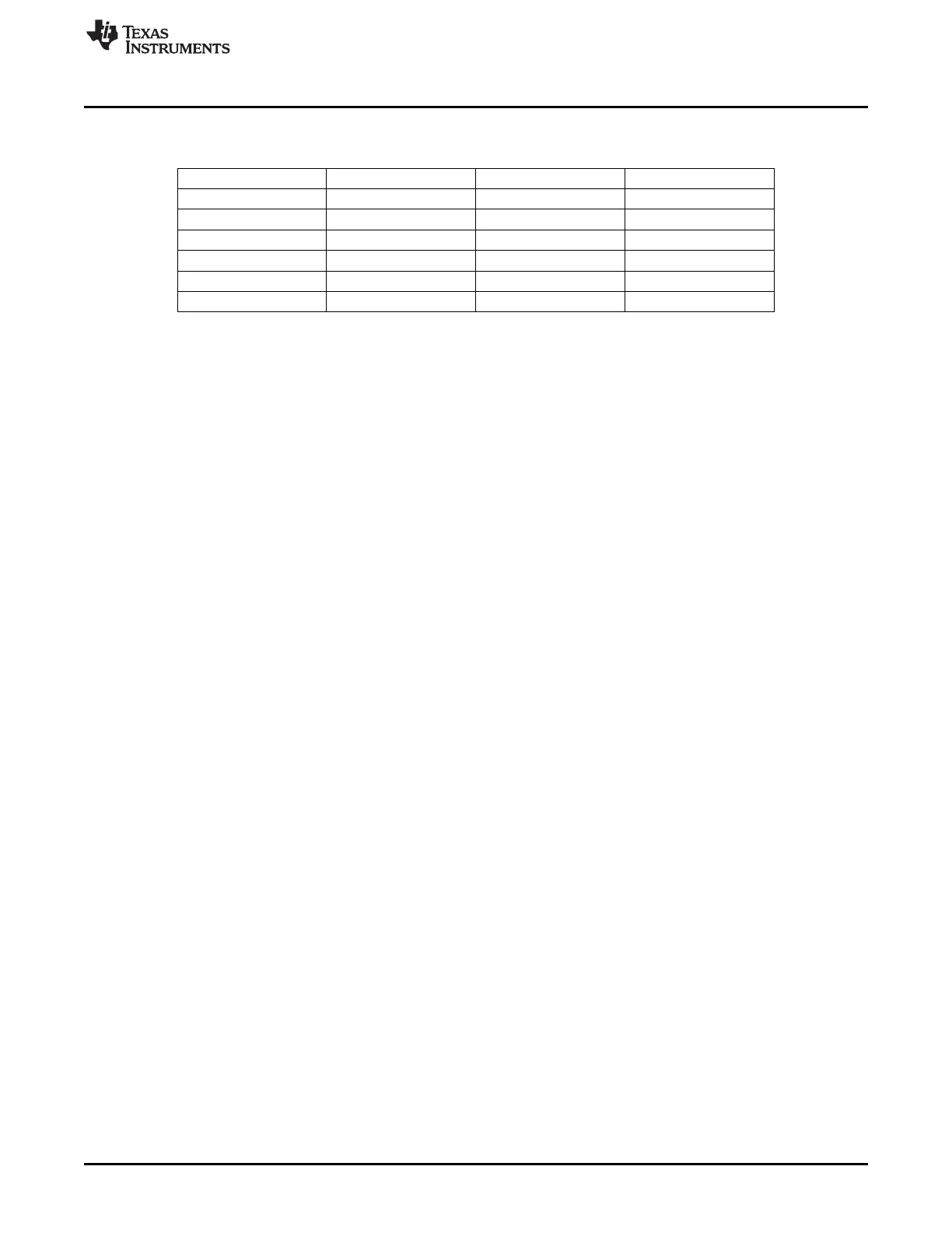
Table 17-1. Commonly Used Baud-Rate Settings for 32 MHz System Clock
(continued)
Baud Rate (bps) UxBAUD.BAUD_M UxGCR.BAUD_E Error (%)
28,800 216 9 0.03
38,400 59 10 0.14
57,600 216 10 0.03
76,800 59 11 0.14
115,200 216 11 0.03
230,400 216 12 0.03
17.5 USART Flushing
The current operation can be aborted by setting the UxUCR.FLUSH register bit. This event stops the
current operation and clears all data buffers. It should be noted that when setting the flush bit in the middle
of a TX/RX bit, the flushing does not take place until this bit has ended (buffers are cleared immediately,
but timers keeping knowledge of bit duration are not). Thus, using the flush bit should either be aligned
with USART interrupts or use a wait time of one bit duration at the current baud rate before updated data
or configuration can be received by the USART.
17.6 USART Interrupts
Each USART has two interrupts. These are the RX complete interrupt (URXx) and the TX interrupt
(UTXx). The TX interrupt is triggered when transmission starts and the data buffer is offloaded.
The USART interrupt enable bits are found in the IEN0 and IEN2 registers. The interrupt flags are located
in the TCON and IRCON2 registers. See Section 2.5 for details of these registers. The interrupt enables
and flags are summarized as follows.
Interrupt enables:
• USART0 RX: IEN0.URX0IE
• USART1 RX: IEN0.URX1IE
• USART0 TX: IEN2.UTX0IE
• USART1 TX: IEN2.UTX1IE
Interrupt flags:
• USART0 RX: TCON.URX0IF
• USART1 RX: TCON.URX1IF
• USART0 TX: IRCON2.UTX0IF
• USART1 TX: IRCON2.UTX1IF
17.7 USART DMA Triggers
There are two DMA triggers associated with each USART. The DMA triggers are activated by RX
complete and TX complete events, i.e., the same events as the USART interrupt requests. A DMA
channel can be configured using a USART receive/transmit buffer, UxDBUF, as source or destination
address.
See Table 8-1 for an overview of the DMA triggers.
17.8 USART Registers
The registers for the USART are described in this section. For each USART there are five registers
consisting of the following (x refers to the USART number, i.e., 0 or 1):
• UxCSR, USART x control and status
• UxUCR, USART x UART control
167
SWRU191C–April 2009–Revised January 2012 USART
Submit Documentation Feedback
Copyright © 2009–2012, Texas Instruments Incorporated
 Loading...


