www.ti.com
Accessing Timer 1 Registers as Array
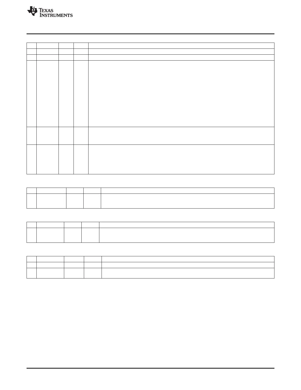
T1CCTL4 (0x62A4) – Timer 1 Channel 4 Capture/Compare Control
Bit Name Reset R/W Description
7
RFIRQ
0 R/W When set, use RF interrupt for capture instead of regular capture input.
6
IM
1 R/W Channel 4 interrupt mask. Enables interrupt request when set.
5:3
CMP[2:0]
000 R/W Channel 4 compare mode select. Selects action on output when timer value equals compare value in
T1CC4.
000: Set output on compare
001: Clear output on compare
010: Toggle output on compare
011: Set output on compare-up, clear on compare down in up-down mode. Otherwise set output on
compare, clear on 0.
100: Clear output on compare-up, set on compare down in up-down mode. Otherwise clear output
on compare, set on 0.
101:
Clear when equal T1CC0, set when equal T1CC4
110:
Set when equal T1CC0, clear when equal T1CC4
111:
Initialize output pin. CMP[2:0] is not changed.
2
MODE
0 R/W Mode. Select Timer 1 channel 4 capture or compare mode
0: Capture mode
1: Compare mode
1:0
CAP[1:0]
00 R/W Channel 4 capture-mode select
00: No capture
01: Capture on rising edge
10: Capture on falling edge
11: Capture on all edges
T1CC4H (0x62AF) – Timer 1 Channel 4 Capture/Compare Value, High
Bit Name Reset R/W Description
7:0
T1CC4[15:8]
0x00 R/W Timer 1 channel 4 capture/compare value high-order byte. Writing to this register when
T1CCTL4.MODE = 1 (compare mode) causes the T1CC4[15:0] update to the written value to be
delayed until T1CNT = 0x0000.
T1CC4L (0x62AE) – Timer 1 Channel 4 Capture/Compare Value, Low
Bit Name Reset R/W Description
7:0
T1CC4[7:0]
0x00 R/W Timer 1 channel 4 capture/compare value low-order byte. Data written to this register is stored in
a buffer but not written to T1CC4[7:0] until, and at the same time as, a later write to T1CC4H
takes effect.
IRCTL (0x6281) – Timer 1 IR Generation Control
Bit Name Reset R/W Description
7:1 – 0000 000 R/W Reserved
0
IRGEN
0 R/W When this bit is set, a connection between Timer 3 channel 1 and Timer 1 tick input is made so
that the timers can be used to generate modulated IR codes (see also Section 9.9).
9.13 Accessing Timer 1 Registers as Array
The Timer 1 capture/compare channel registers can be accessed as a contiguous region in the XDATA
memory space. This facilitates accessing the registers as a simple indexed structure. The five
capture/compare control registers are mapped to 0x62A0–0x62A4. The 16-bit capture/compare values are
mapped to 0x62A6–0x62AF; 0x62A5 is unused.
123
SWRU191C–April 2009–Revised January 2012 Timer 1 (16-Bit Timer)
Submit Documentation Feedback
Copyright © 2009–2012, Texas Instruments Incorporated
 Loading...


