EN
–
+
CMPCTL.EN
ENB
ENB
Pad I/O Driver
Pad I/O Driver
0
1
S0385-01
Edge Detector
for P0_5
Analog
Comparator
P0_4
(Pad)
P0_5
(Pad)
Description
www.ti.com
19.1 Description
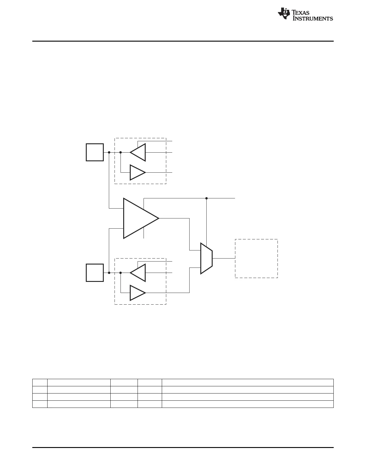
The analog comparator is connected to the I/O pins as follows:
• The positive input pin is connected to P0_5.
• The negative input pin is connected to P0_4.
• The output can be read from CMPCTL.OUTPUT.
The comparator pins must be configured as analog pins by setting bits APCFG[5:4] to 1. The
CMPCTL.EN bit is used to enable/disable the comparator. The output from the comparator is connected
internally to the edge detector that controls P0IFG[5]. This makes it possible to associate an I/O interrupt
with a rising/falling edge on the comparator output. When enabled, the comparator remains active while in
power mode 2 or 3. Thus, it is possible to wake up from power mode 2/3 on a rising or falling edge on the
comparator output.
Figure 19-1. Analog Comparator
19.2 Register
This section describes the registers for the analog comparator.
A
CMPCTL (0x62D0) – Analog Comparator Control and Status
Bit Name Reset R/W Description
7:2 – 0000 00 R0 Reserved
1
EN
0 R/W Comparator enable
0
OUTPUT
0 R Comparator output
176
Analog Comparator SWRU191C–April 2009–Revised January 2012
Submit Documentation Feedback
Copyright © 2009–2012, Texas Instruments Incorporated
 Loading...


