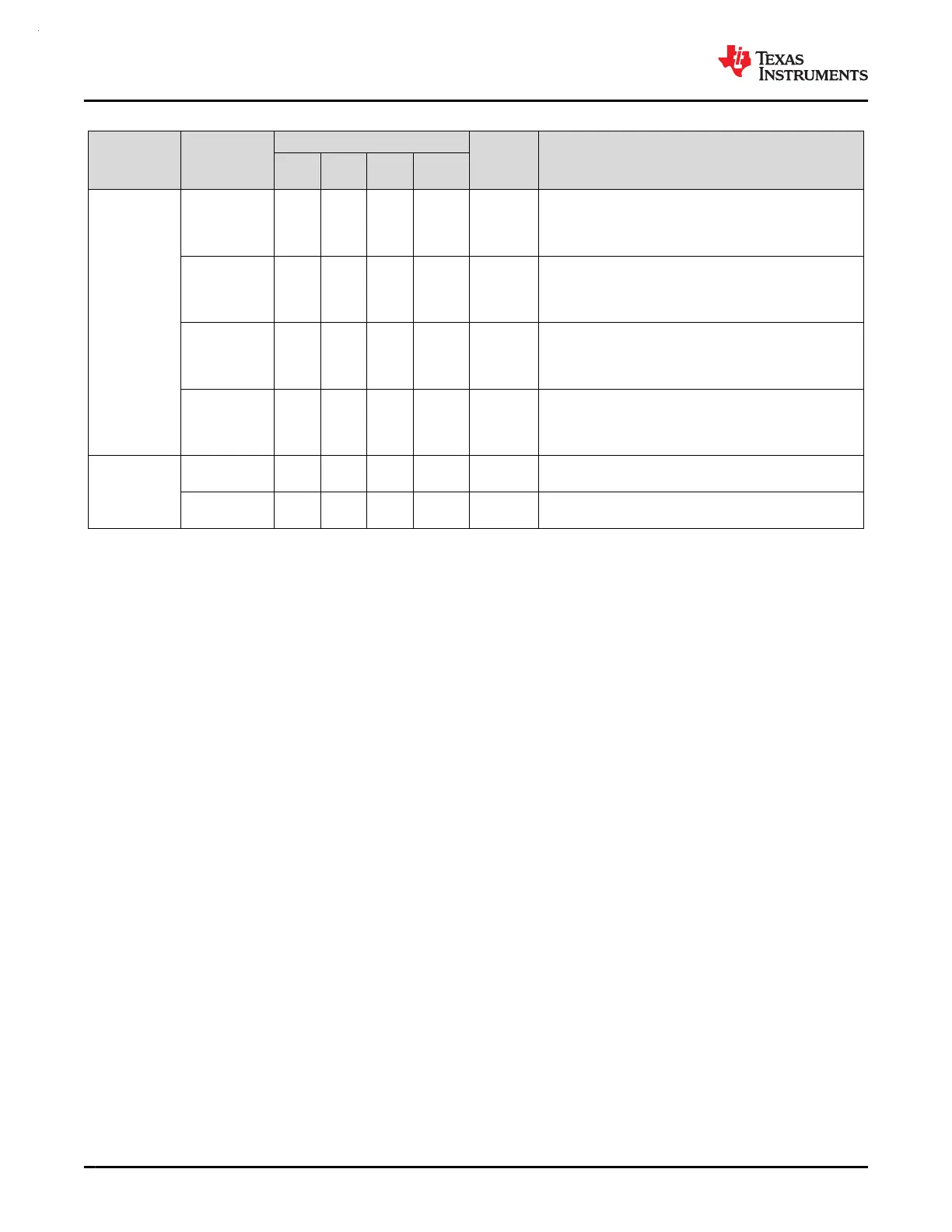
Table 6-3. Signal Descriptions (continued)
FUNCTION
SIGNAL
NAME
PIN NO.
(1)
PIN TYPE
(2)
DESCRIPTION
64 PM
48 PT,
RGZ
32
RHB
28
DGS28
UART
UART3_TX
7
30
50
64
14
29
46
18
30
1
17
O UART3 transmit data
UART3_RX
1
6
26
51
15
28
45
17
29
28 I UART3 receive data
UART3_CTS
3
5
24
52
25
27
43
16
27
26 I UART3 "clear to send" flow control input
UART3_RTS
4
6
25
53
26
28
44
17
28
27 O UART3 "request to send" flow control output
Voltage
Reference
(3)
VREF+ 24 43 27 26 I/O
Voltage reference (VREF) power supply - external
reference input / internal reference output
VREF- 17 39 25 24 I/O
Voltage reference (VREF) ground supply - external
reference input / internal reference output
(1) – = not available
(2) I = input, O = output, I/O = input or output, P = power
(3) When using VREF+/- to bring in an external voltage reference for analog peripherals such as the ADC, a decoupling capacitor must be
placed on VREF+ to VREF-/GND with a capacitance based on the external reference source
MSPM0G3507, MSPM0G3506, MSPM0G3505
SLASEX6A – FEBRUARY 2023 – REVISED JUNE 2023
www.ti.com
26 Submit Document Feedback
Copyright © 2023 Texas Instruments Incorporated
Product Folder Links: MSPM0G3507 MSPM0G3506 MSPM0G3505
 Loading...


