iCNC PERFORMANCE
Manual 0-5399 NESTING 5-45
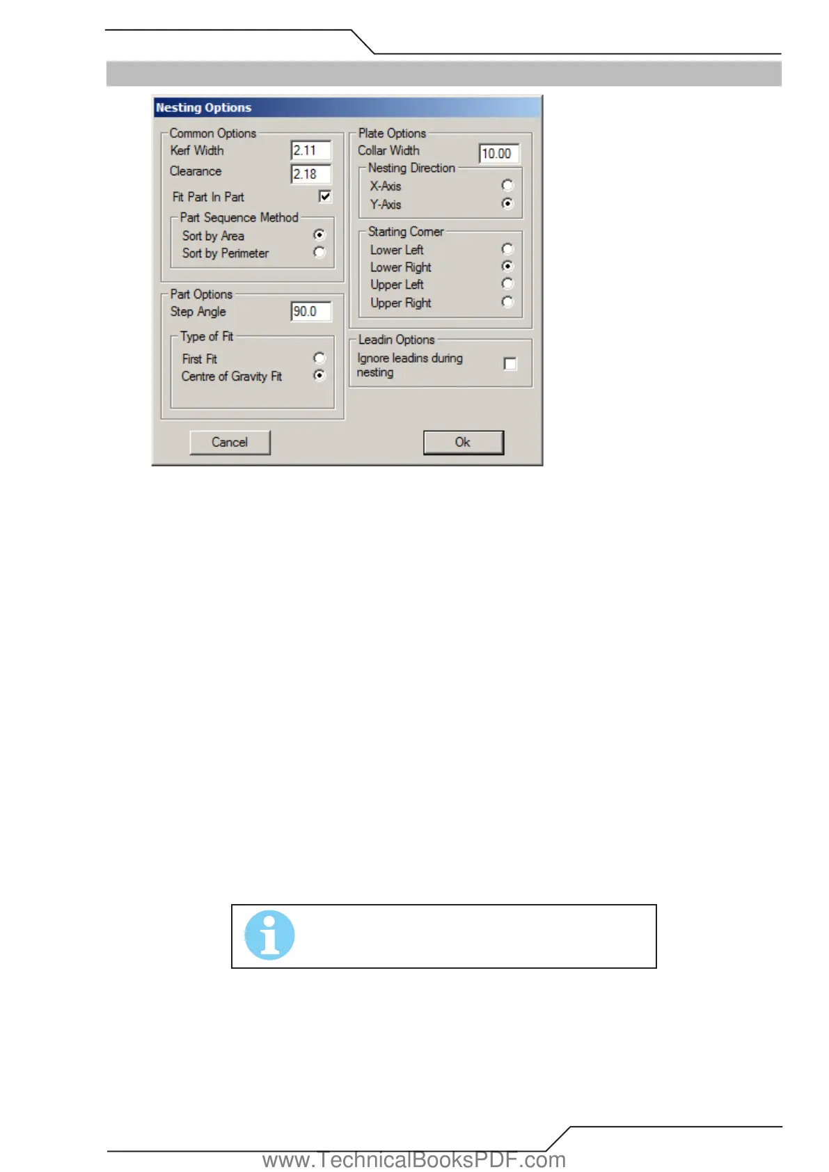
5.16 Nesting Options
Common options
• Kerf width The kerf width of the selected cutting process.
• Clearance Specifies the minimum distance always to be left between shapes nested on a plate. If this variable is set to zero (0), the
program places them as close to each other as the kerf width allows.
• Fit Part in Part If selected, the program will attempt to place smaller shapes to the holes of the larger ones.
• Part sequence method Shapes can be nested either in an order set by their surface area or their perimeter. If sort by area is chosen,
then those shapes that have largest surface area will be nested first. When sort by perimeter is chosen, the shapes which have
largest perimeter will be nested first. (A shape which is long, but thin, has a great perimeter, but a small surface area.)
Part Options
• Step angle When nesting shapes onto a plate, ProMotion® Nest attempts to place them on it in different positions. Between each
attempt, ProMotion® Nest rotates the shapes as many degrees as given here. A full circle is 360 degrees. Thus, if this variable is
set to 90, the shapes will be attempted to nest in four different positions; if set to 1 degree ProMotion® Nest tries 360 different
positions. Obviously, the smaller the step angle, the better the result, but a small step angle naturally extends the nesting time.
• Type of Fit Shapes can be nested according to two principles, the First Fit and the Center of Gravity Fit. The First Fit setting tells
ProMotion® Nestto place the shape in the first position it determines will work. The Center of Gravity Fit setting tells ProMotion®
Nest to calculate the position where the center of gravity of the shape is as close to the bottom line of the plate as possible. The
bottom line of the plate is selected in the Plate Options (see below).
Plate Options
• Collar width Sets the distance to be left between the plate’s edges and the outermost shapes. In other words, shapes are never to
be placed closer to the edge of the plate than stated in this variable.
• Nesting direction This option sets the axis on what the nesting process proceeds. Whether the nesting process proceeds to the
left or the right depends on the starting corner setting.
• Starting corner Determines which corner the nesting begins at.
NOTE!
If Clearance is greater than Collar width, then Collar width is set
to same as Clearance.
Leadin Options
• Ignore leadins during nesting When selected all leadins and leadouts are ignored during the nesting process. This is a useful option
if shapes are going to be nested and then bridged. Bridging removes extra leadins that can be ignored.
www.TechnicalBooksPDF.com