iCNC PERFORMANCE
Manual 0-5399 NESTING 5-9
Required area shows the minimum width and length of the plate that the current parts need when multiplied and used the given
parameters kerf, clearance and collar.
You can either type in a number to rows/columns or click the on the grid to create desired number of copies.
The crosshairs define the 0 reference point for the parts.
NOTE!
Kerf, clearance and collar are the same that are in the Nesting Options. If you change them here,
their values are applied to the nesting options as well. The only exception is the clearance. If the
clearance is negative here, automatic nesting still uses zero as the minimum clearance.
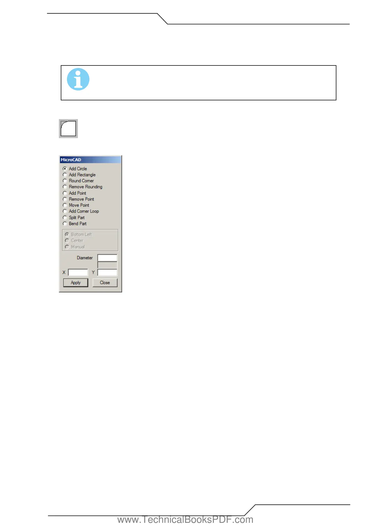
5.3.6 MicroCAD
Use this tool to edit profiles. The tools are described below.
Add Circle
Type the diameter and the coordinates of the center point to the corresponding text fields. Click Apply and the circle is added to the
shape. The new circle will be the first one in the cutting order.
Add Rectangle
First choose the center point or the bottom left corner of the rectangle. Enter the length, width and the coordinates in the corresponding
text fields. Click Apply and the rectangle is added to the shape. The new rectangle will be the first one in the cutting order.
Round Corner
Insert the radius of the rounding to the Radius text field and click Apply to verify the radius. Moving the cursor over a corner changes
the cursor to a cross. Click the corner and it will be rounded with the radius you just set.
Remove Rounding
Changes arcs to two (2) lines. Move the mouse cursor over an arc and it changes to a cross. Click to remove rounding.
Add Point
Adds points (lines) to a shape. If the shape contains open profiles, the line is drawn from the last point of the first open profile to the
point you added. If there are no open profiles, then new line (and profile) is created from the 0,0 point to the point you added. Adding
new points is simple. Just type in the coordinates and click Apply.
Remove Point
Removes single points from a profile. Move the mouse cursor over a point and it changes to a cross. Click and the point is removed.
If the point was the last or the first point of the profile, then the entire element is removed, otherwise the previous and the next point
are connected with a line.
www.TechnicalBooksPDF.com