13
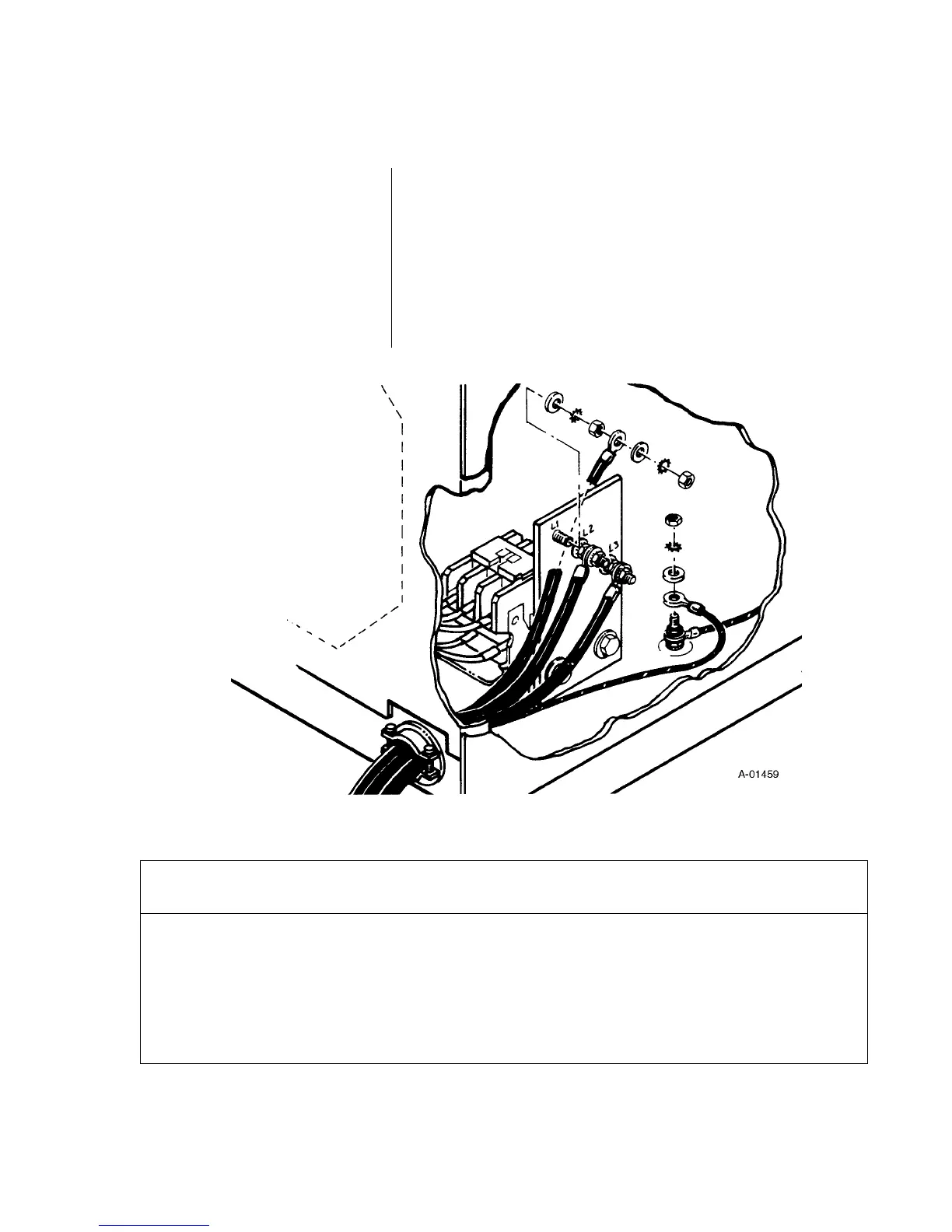
2. Connect the power cable to the appropriate three-phase
power source. Input power cable connections to the
contactors are shown in Figure 2-F.
3. Check that power source meets fuse and wiring require-
ments (see Table 2-A below).
4. Connect the work cable securely to the workpiece. Also
be sure the workpiece is connected to a good electrical
ground.
5. Before operating the system, check the torch for proper
assembly (see page 27).
2.3 INSTALLATION (continued)
Input Power Supply
(continued)
INSTALLATION
Work Cable Connection
Table 2-A Line Voltages, Circuit Protection and Recommended Wire Size
(Based on Table 310-16, 1981 National Electric Code).
Voltage Power Input Current* Frequency Phase Recommended
(Volts) (kVA) (Amps) (Hz) Fuse Size Wire Size
200 26 74 50 or 60 3 90 amps AWG 6
220 26 68 50 or 60 3 90 amps AWG 6
380 26 40 50 3 50 amps AWG 8
415 26 37 50 3 45 amps AWG 8
460 26 33 60 3 40 amps AWG 8
500 26 30 50 3 40 amps AWG 8
575 26 26 60 3 35 amps AWG 10
Figure 2-F Input Power Connections
 Loading...