Message Center: Displays the system status (Mode) at all times. Displays
SYSTEM OK during normal operation, or alarm messages if the system
detects an alarm condition. See Section 4, Alarms.
Upper and Lower Displays: These 7 segment displays vary depending
upon the options present and the configuration chosen. The upper dis-
play can display temp or RH, or toggle between them. The bottom dis-
play shows CO
2 continuously.
Warning Single and stacked units must be installed against a wall or
similar structure. Maintain a three-inch clearance behind the incubator for
electrical and gas hook-ups.
s
1. Locate the unit on a firm level surface capable of supporting the unit’s
weight of 205 lbs.
2. Locate the unit away from doors and windows and heating and air
conditioning ducts.
3. Lift the unit only by the sides of the cabinet base . Do not attempt to
lift it by the front and back . This places stress on the outer door
hinges.
Caution When stacking incubators, the direct heat incubator must be the
top unit. Never stack a water-jacketed incubator on top of a Model 310
Series unit.
s
Warning With incubators in a stacked configuration, do not leave both
exterior doors open at the same time.
s
Warning If the units have been in operation, shut them both off and
disconnect from the power source before beginning any service work. s
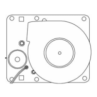
Note Two stacking brackets (shown at right) are included
in the parts bag shipped with each incubator.
s
1-4 Model 310 Series DH Incubator Thermo Scientific
Section 1
Installation and Start-Up
Displays
Installing the
Incubator
Stacking the Incubators
Figure 1-3.
Stacking Brackets