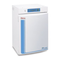
1. Remove and discard the slotted head
screws on the top of the bottom incubator
(Figure 1-4). Replace with 5/16 HH bolts
and flatwashers included in the stacking
kit. Do not tighten.
2. Remove the kickplate from below the door on the top incubator
(Figure 1-5). Two Phillips screws secure the plate. Note the notches at
the base of the incubator frame.
3. Disconnect the door cable from the connector behind the plate. Lift
the door off the hinge pins and set it aside. The hinge pins are not
attached to the brackets and may fall out when the door is lifted off.
4. Unscrew and remove the leveling feet from the top unit and lift it onto
the bottom unit, offsetting the base of the top unit approximately 2-3
inches behind the screws identified by the arrows in Figure 1-4.
Warning This incubator weighs 205 lbs. Have sufficient personnel
available when lifting. Lift the unit only by the sides of the cabinet base.
Do not attempt to lift it by the front and back as this places stress on the
outer door hinge.
s
5. Align the sides of the top unit with the bottom unit and slide the top
unit forward until the notches in the base of the top unit align with
the bolts in the top of the bottom unit. The flatwashers should slide
over the base frame. Tighten bolts.
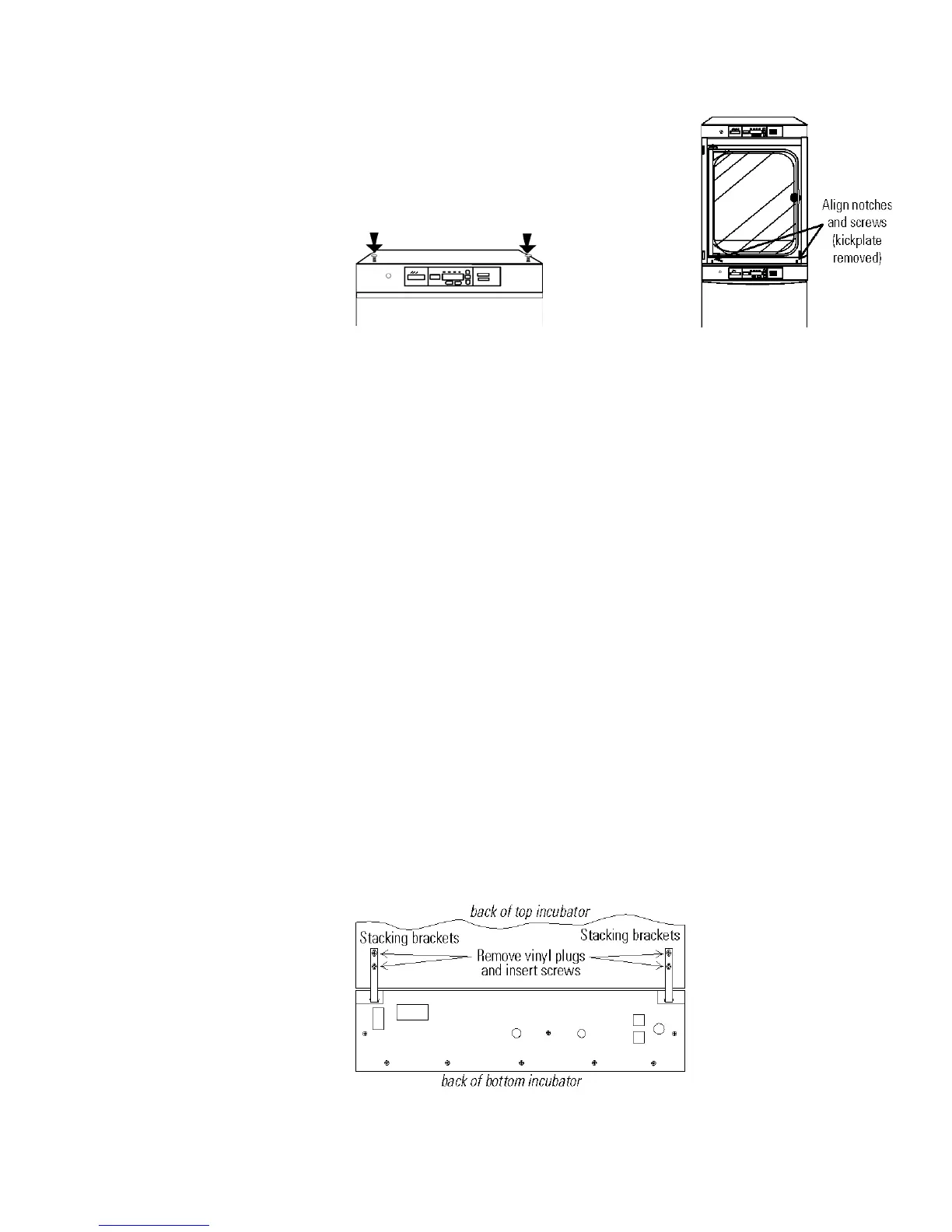
6. Remove the four nylon plugs on the lower back of the upper incubator.
7. Insert the stacking brackets into the slots on the back of the control
panel of the bottom unit as shown in Figure 1-6.
Model 310 Series DH Incubator 1-5Thermo Scientific
Section 1
Installation and Start-Up
Stacking (continued)
Figure 1-4. Slotted Head Screws
Figure 1-5. Align
Figure 1-6. Brackets Installed