All incubator models can be purchased with the RS485 communications
option (P/N 190523). This option allows the incubator to be directly
connected to a Model 1535 alarm system without the use of a
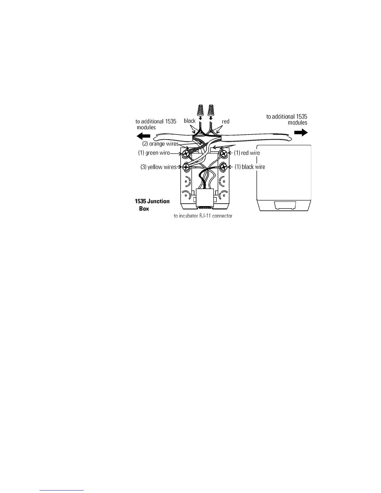
communications module. A junction box is provided with each RS485
option. See Figure 6-2 for wiring details. Figure 6-3 shows the RS485
connector location on the back of the incubator cabinet.
To allow the incubator and the 1535 to communicate, an address must be
allocated on the 1535. Refer to Section 5.8 of the 1535 operating manual.
The same address number must be assigned to the incubator. Refer to
Section 3 of this manual.
Warning The electronics section contains hazardous voltages. Only
qualified personnel should access this area.
s
The analog output board option (P/N 190512, 190543, 190544) allows
the incubator to output analog signals representing the air temperature of
the cabinet, CO
2 content, and relative humidity, depending upon which
systems are in the incubator. There are three different analog output board
options available : 0-1V, 0-5V, or 4-20mA signals. Negative display
readings will output 0V. The outputs do not have isolated grounds. Refer
to Table 6-1 for output specifications of the three boards.
For the 0-1V and 0-5V boards, the recording device must supply a load
>/= 1000 ohm. For the 4-20mA board, the recording device must supply a
load of </= 100 ohm.
6-2 Model 310 Series DH Incubator Thermo Scientific
Section 6
Factory Options
Connect RS485
Interface
Connecting the
Analog Output Boards
Figure 6-2. RS485 Wiring