Model 310 Series DH Incubator 6-3Thermo Scientific
Section 6
Factory Options
To wire in the analog output board, a shielded 22 gauge, 3-conductor wire
(P/N 73041) is recommended, with the maximum length being 50 feet
(15.2m). This wire is readily available from other vendors including Alpha
P/N 2403 and Deerborn P/N 972203.
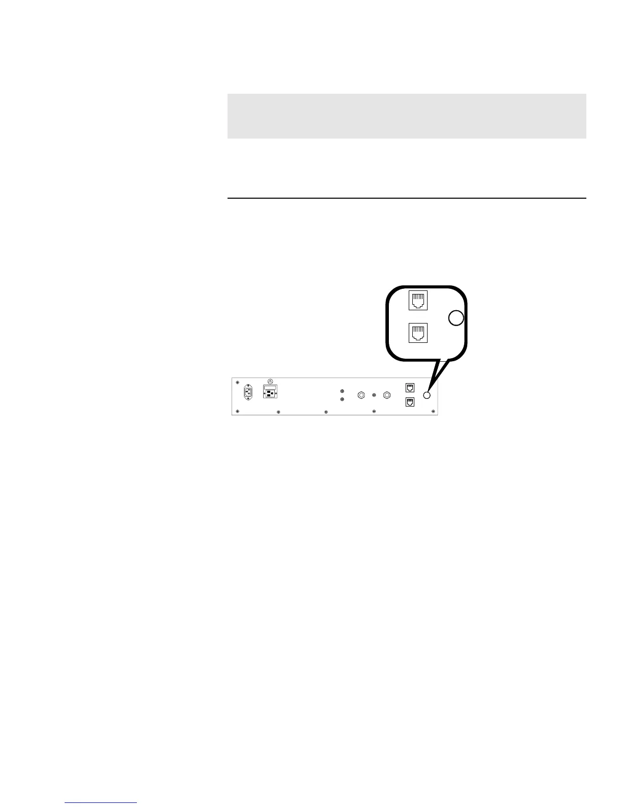
Figure 6-3. Auxiliary Through-Port on Back Panel
Caution Accuracy of the output at the board terminal strip to the
incubator display is ±1 unit. There is no calibration from the incubator.
Calibration to the incubator display must be at the instrument connected
to the output board.
s
To install the analog board:
1. Turn off the incubator and unplug it from the wall outlet.
2. Remove the top of the electronics section. Refer to Section 5 of this
manual.*
3. Locate the Analog Output board, Figure 6-4 and Figure 5-8.
* Alternate access to the electronics is to open the outer door and remove the two
screws in the upper corners of the cabinet just under the display top. Lifting up
the top section, the electronics drawer can be pulled out to the limit of the
internal wiring.
75 WATTS MAX.
15 p.s.i. Regulated
15 p.s.i. Regulated
190512 4-20 mA
Output Scaling
4-20 mA Equals
190544 0-1V
Output Scaling
0-1 V Equals
190543 0-5V
Output Scaling
0-5V Equals
Temperature 0.0-100.0°C 0.0-100.0°C 0.0-100.0°C
RH 0-100 %RH 0-100 %RH 0-100 %RH
CO2 0.0-100.0 %CO2 0-100.0 %CO2 0-100.0 %CO2
Table 6-1. Analog Output Boards
Connect Analog
Output Boards (cont.)