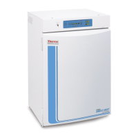
Figure 6-4. Connector Terminals
4. Each system monitored (Temp, CO
2, RH) requires two conductors
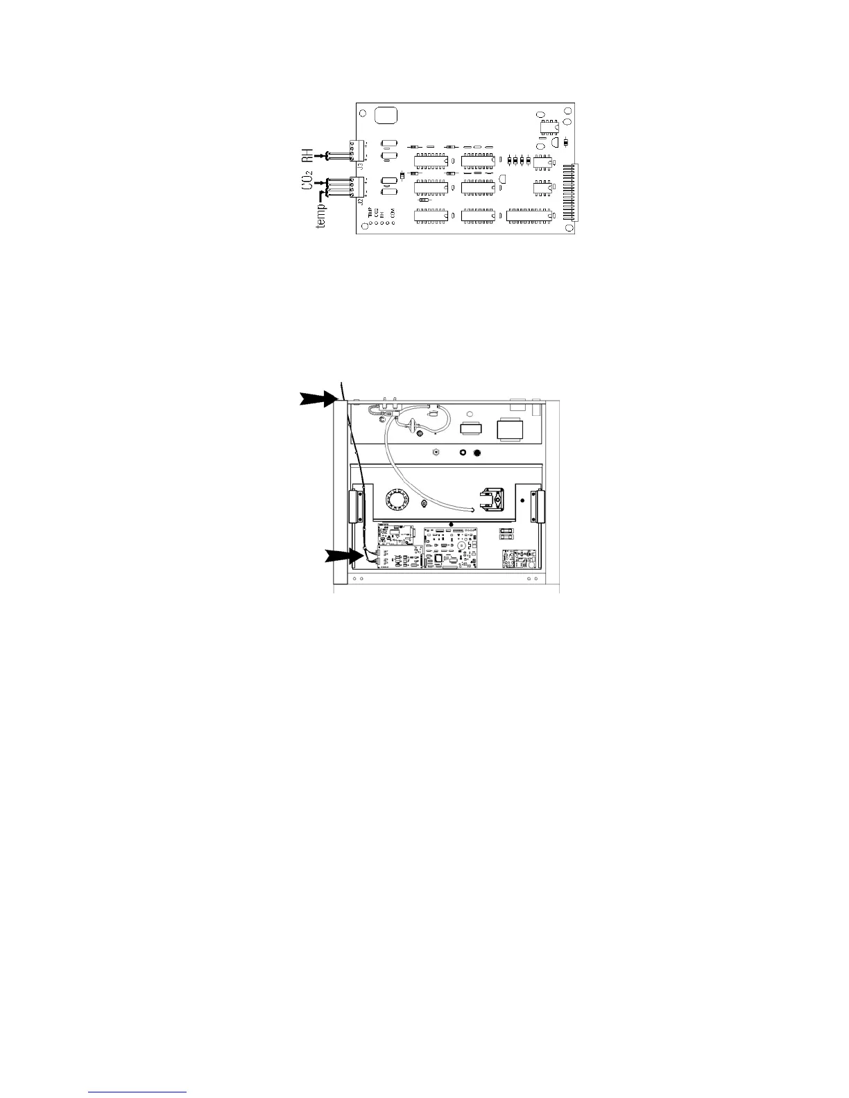
(refer to Figure 6-4). Feed the wires through the auxiliary wire
through-port on the back panel. This port is a circular fitting adjacent
to the remote alarm and RS485 connectors as illustrated in Figure 6-3.
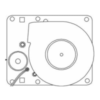
The wire routing is shown by the black arrows in Figure 6-5.
5. Strip the ends of each conductor and wire it to the appropriate
terminals of connectors J2 and/or J3 on the analog board. Refer to
Figure 6-4.
6. When wiring is completed, slide in the electronics drawer or the
replace the sheet metal cabinet top.
7. Replace the screws removed earlier and return the unit to service.
6-4 Model 310 Series DH Incubator Thermo Scientific
Section 6
Factory Options
Figure 6-5. Wire Routing
Connect Analog
Output Boards (cont.)