Warning CO2 can be lethal in high concentrations. Refer to warnings in
Section 1 of this manual. s
The Model 310 Series incubators can be equipped with a built-in Gas
Guard system (P/N 190640) that will operate with a CO
2 gas supply. The
Gas Guard uses two pressure switches to continuously monitor the
pressures of two independent CO
2 supplies and automatically switches
from one supply to the other when the supply pressure drops below 10
psig (0.690 bar). The Gas Guard’s design does not facilitate use by
multiple incubators.
The CO
2 gas supplies must be equipped with two-stage pressure regulators
with gauges. The high pressure gauge at the tank should have a 0-2000
psig range and the low pressure gauge should have a 0-30 psig range. The
gas supply to the incubator must be maintained at 15 psig (1.034 bar), ±5
psig. Gas pressures below 15 psig will cause nuisance alarms to occur on
incubators equipped with the built-in Gas Guard.
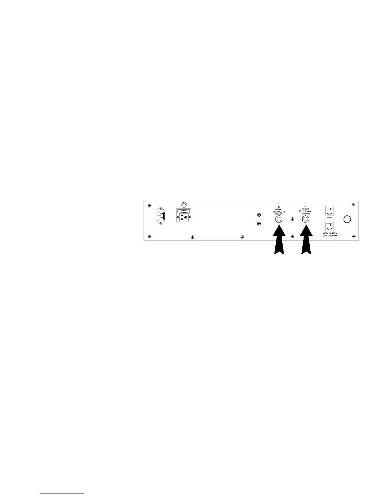
The CO
2 inlets for the Gas Guard are located on the back of the cabinet.
Using 1/4” ID tubing, connect one of the CO
2 supply tanks to the fitting
labeled CO2 Inlet #1 Tank. Connect the second CO
2 supply tank to the
fitting labeled CO2 Inlet #2 Tank. Install 3/8” hose clamps to secure the
1/4” ID tubing to the fittings on the back of the drawer. (Refer to Figure
6-6.)
The built-in Gas Guard is turned ON when shipped from the factory. In
addition, the Tank Sel for the Gas Guard is specified as Tank 1 when
shipped. Refer to Section 3, Configuration, to de-activate the Gas Guard
or change the Tank Sel from #1 to #2. If the Gas Guard system is not
used, the incubator will function normally by supplying CO
2 from the
supply tank connected to Inlet #1.
Model 310 Series DH Incubator 6-5Thermo Scientific
Section 6
Factory Options
Figure 6-6. Connect Gas Supplies
De-activating the Gas
Guard
Connecting the CO
2 Gas
Supplies
CO2 Gas Guard