381Camera Basics
© 2010 Thorlabs
9.13
Interface Basics
9.13.1
History and development
The Universal Serial Bus (USB) is an interface which allows easily connection of different devices to
a PC. All data transmission is controlled by the PC and no special interface controller is required.
Further advantages of USB are:
The system does not have to be shut down when connecting USB devices (hot plugging).
USB devices can be supplied with voltage from the PC.
The USB standard was developed by a consortium of companies like Compaq, IBM, Intel, Microsoft
and others. Version 1.0 was introduced in 1995, the slightly faster USB1.1 standard followed in
1998.
At first, the USB interface was designed to connect devices such as printers, mice and keyboards.
With the introduction of USB2.0 in 2001 the bus bandwidth increased to 480 MBit/s, making USB2.0
suitable for devices with high data rates (such as mass storage devices, scanners or cameras).
9.13.2
Cable and connection
The maximum length for USB2.0 cables is limited to 5m in order to comply with the specifications.
Longer cables are allowed if high quality material is used.
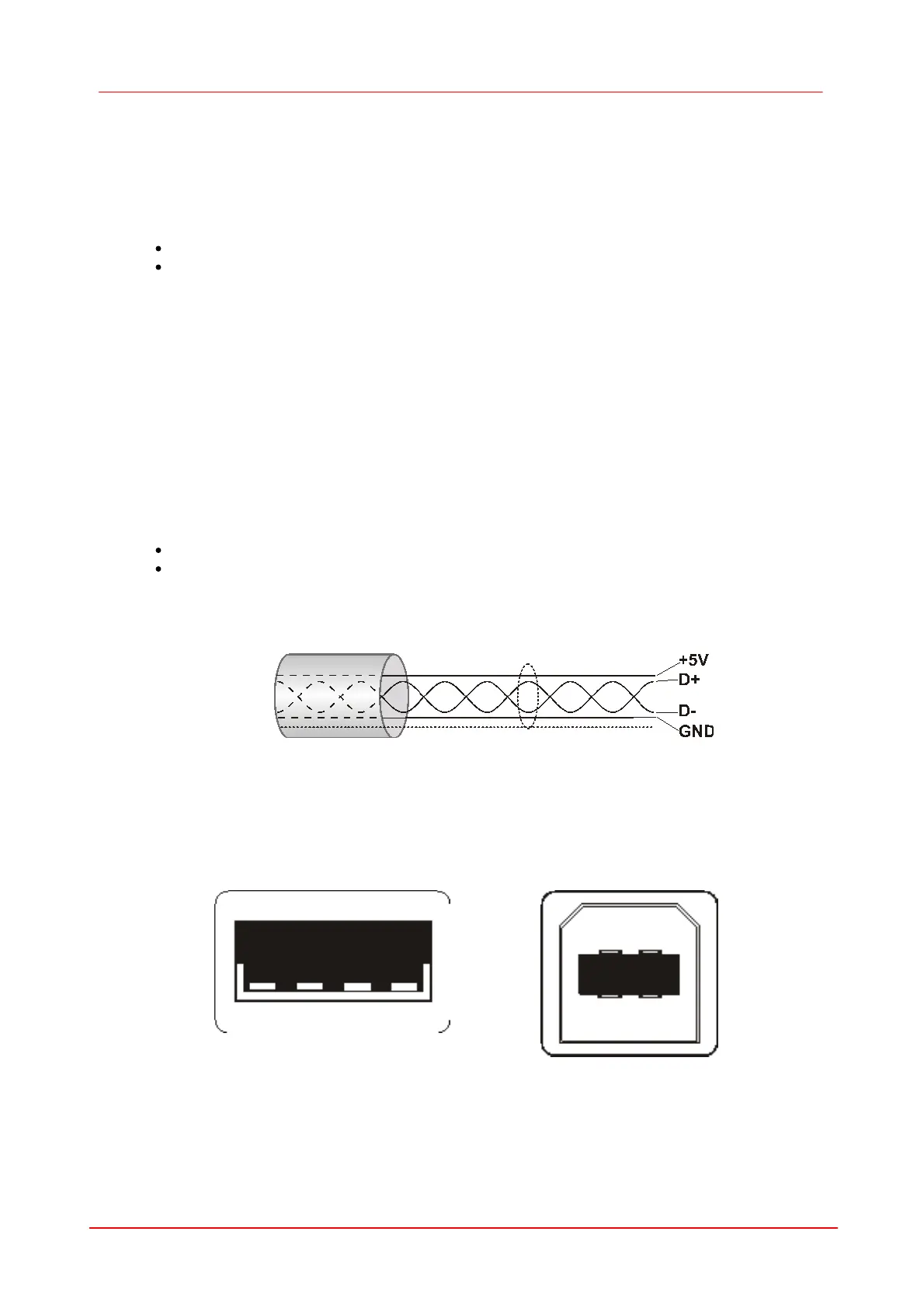
The following illustration shows the structure of a shielded USB cable:
D+/D-: data signalling
+5V/GND: power supply
The USB bus provides a power supply with max. 5V and 500mA. Many USB devices use the bus
power and don’t need external power supply (bus-powered devices).
Figure 80 Structure of a USB of cable
On host side USB cables are equipped with a Standard-A type plug (four pins) and on the device
side either a Standard-B (four pins) or Mini-B plug (five pins with ground). In addition the DCU
cameras offer a nine pin Sub-D connector for DCU camera cables. The additional four pins carry the
camera’s digital input/output signals.
 Loading...