398 DCx camera
© 2010 Thorlabs
10.1.3
I/O Interface
10.1.3.1
Trigger Input Wiring (Trigger)
NOTE
The USB Board Rev. can be read out with the Camera Info
Table 21 Digital input specifications
Trigger pulse width (edge)
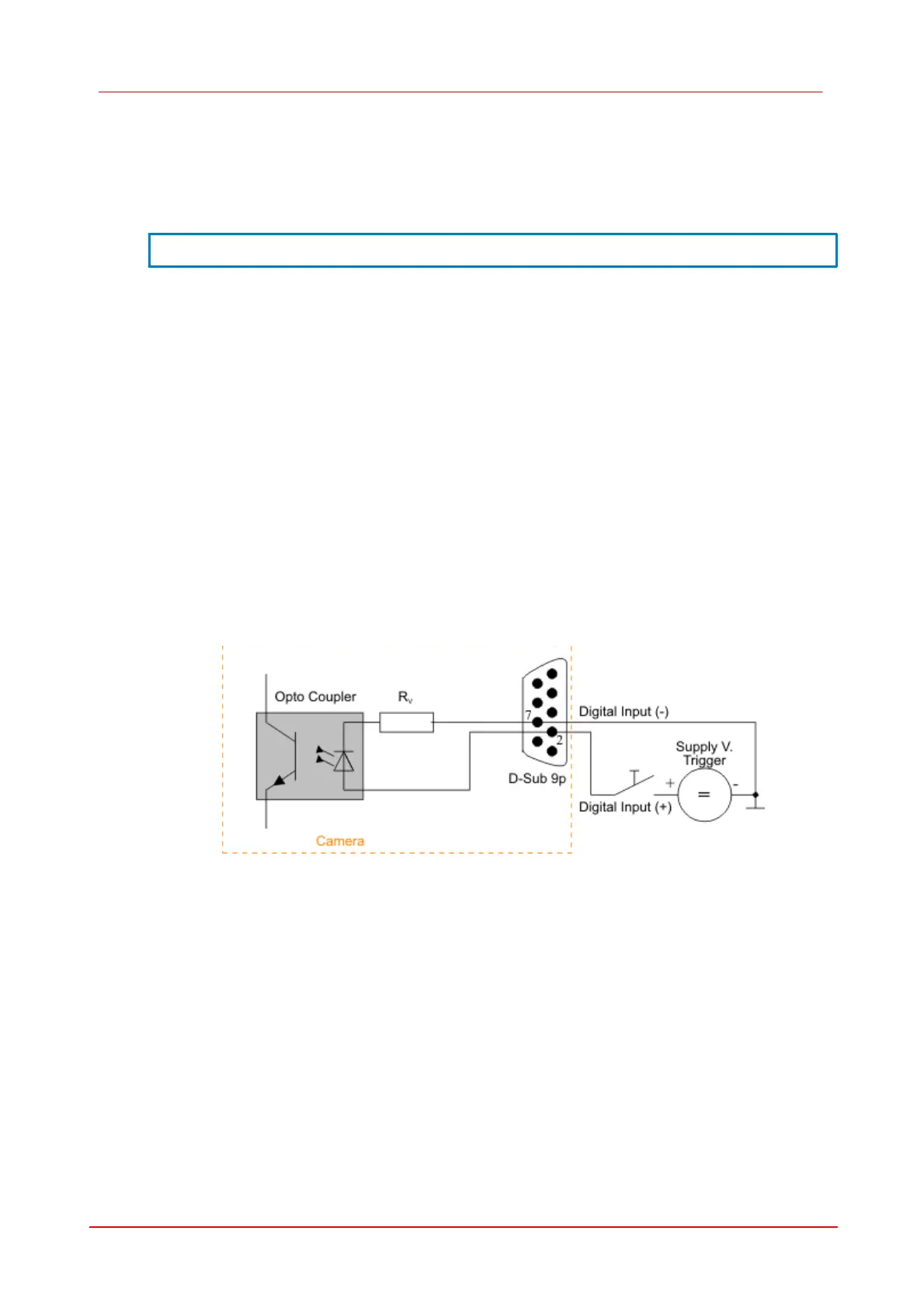
For interpreting the trigger signal, either the positive or the negative edge can be used. The digital
input is galvanically isolated using an opto coupler to protect the camera and the PC against surges.
Only DC voltages may be applied to the digital input.
Figure 102 Trigger connection
10.1.3.2
Digital Output Wiring (Flash)
The flash strobe is optically isolated to DCU and your PC on order to protect your equipment. It is
adapted for voltages up to 24V DC.
The output of the opto coupler can be used as open collector or open emitter output. This means the
strobe can be switched to ground or to a supply voltage. The strobe signal is active, when the
collector emitter switch is closed. Opto couplers solely can switch DC voltages. Do never switch AC
voltages.
In the following table the maximum charges for the output are specified.
 Loading...