© 2016 Thorlabs Scientific Imaging476
DCx Camera Functional Description and SDK Manual
5.5.2 DCC3240x
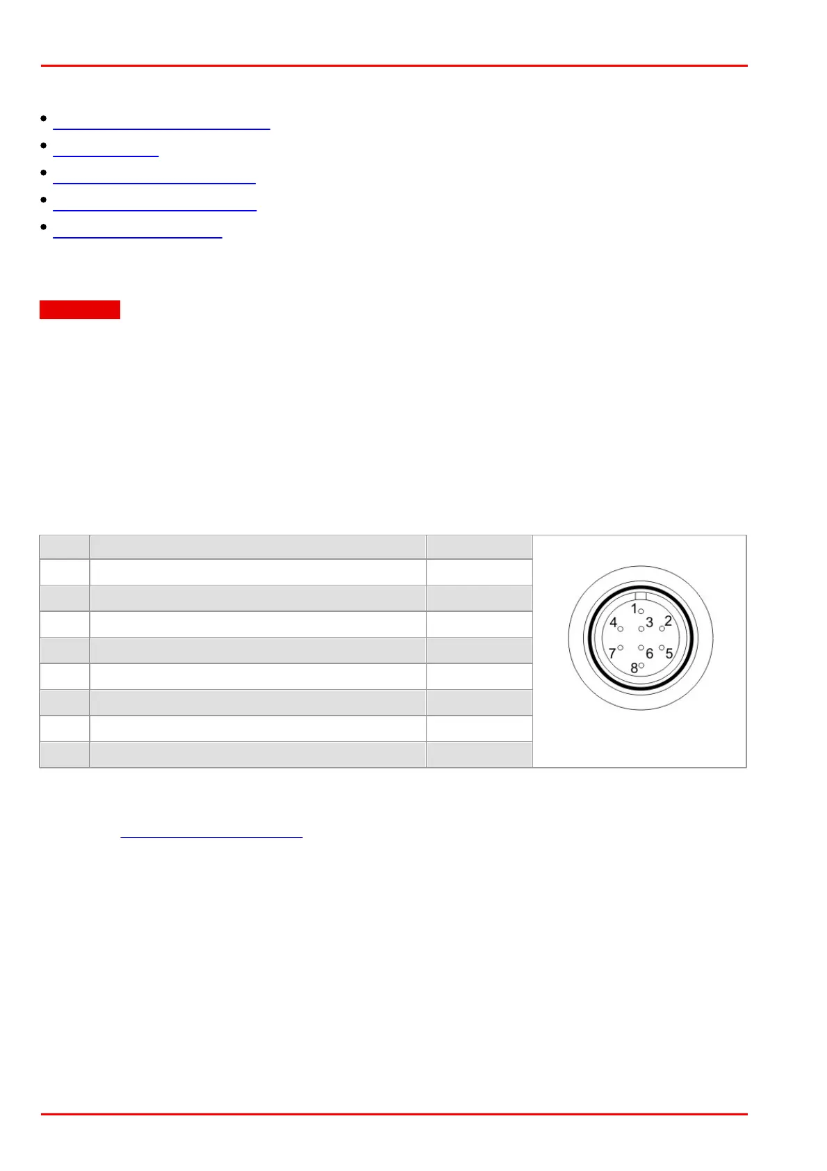
I/O connector Pin Assignment
GPIO Interface
Digital Input (Trigger) Circuit
Digital Output (Flash) Circuit
RS-232 Serial Interface
5.5.2.1 I/O Connector Pin Assignment
Attention
The General Purpose IO are not potential-free and have no protective circuit. Faulty wiring
(overvoltage, undervoltage or inverting the wiring when used as serial interface) can result in a
damage in the electronics.
During operation as serial interface only LVCMOS levels are allowed to the connector pins. To get
a serial RS-232 compliant interface, an external level shifter (LVCMOS/RS-232) is required.
Applying RS-323 levels directly to the pins as well as mixing up the signals RxD and TxD can
destroy the camera electronics!
Pin assignment of the 8-pin Hirose connector HR25 for trigger, flash and GPIO
Hirose connector male,
camera rear view
Flash output, opto-decoupled (-)
Trigger input, opto-decoupled (-)
Flash output, opto-decoupled (+)
Trigger input, opto-decoupled (+)
Output supply voltage, 5 V (100 mA)
For a comprehensive list of all cables and connectors available for DCC3240X cameras, please
refer to the DCC3240X Accessories section.
 Loading...