© 2016 Thorlabs Scientific Imaging
5 Specifications
477
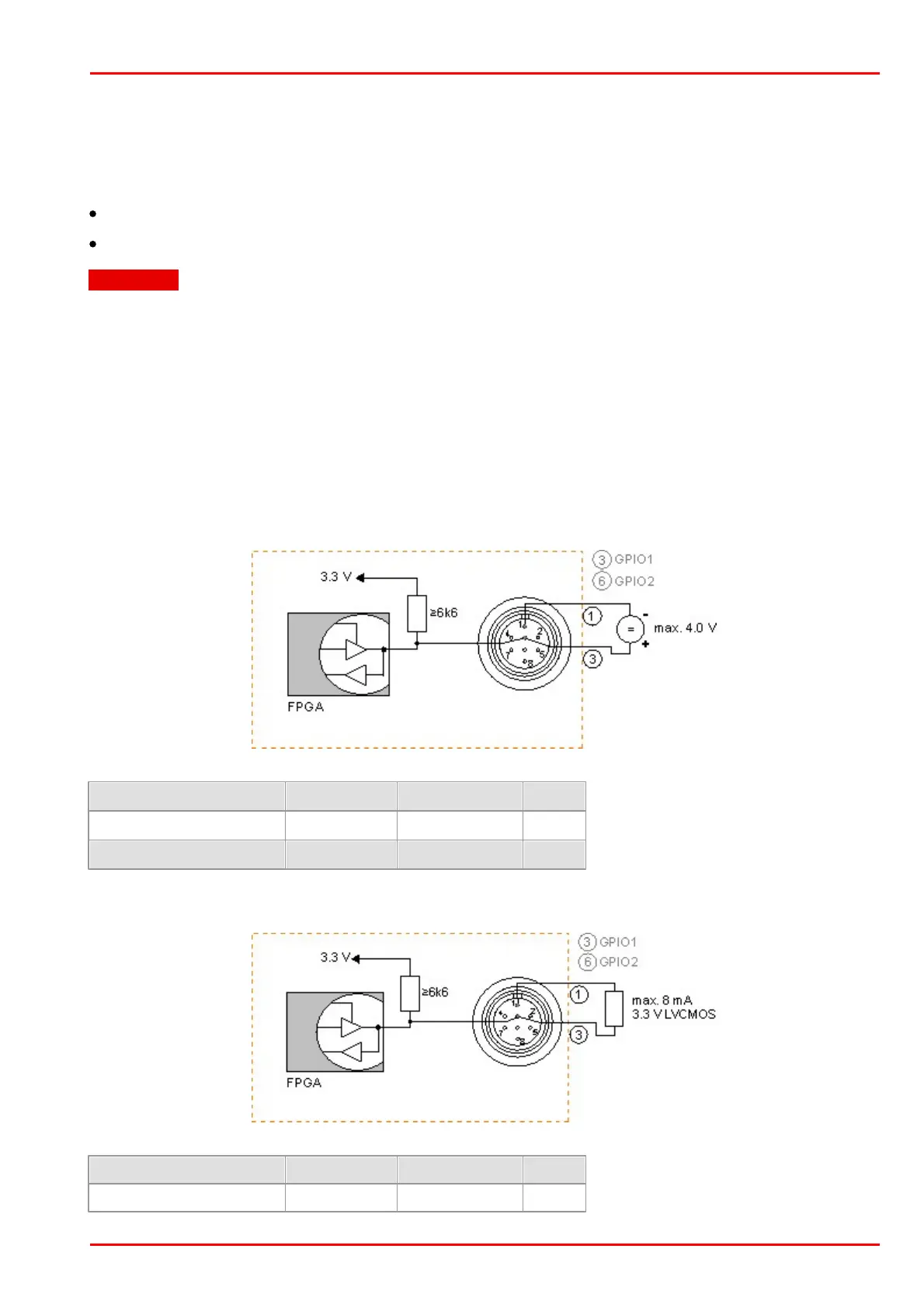
5.5.2.2 GPIO Interface
GPIO specifications
The two GPIOs (General Purpose I/O) can be used as inputs or outputs. This selection is made by
software using the corresponding SDK API functions. Please observe the following criteria:
Input: 3.3 V LVCMOS, max. input voltage 4.0 V
Output: 3.3 V LVCMOS, max. 10 mA
Attention
The General Purpose IO are not potential-free and have no protective circuit. Faulty wiring
(overvoltage, undervoltage or inverting the wiring when used as serial interface) can result in a
damage in the electronics.
During operation as serial interface only LVCMOS levels are allowed to the connector pins. To get
a serial RS-232 compliant interface, an external level shifter (LVCMOS/RS-232) is required.
Applying RS-323 levels directly to the pins as well as mixing up the signals RxD and TxD can
destroy the camera electronics!
GPIO wiring as input
The following figures illustrate GPIO wiring examples.
GPIO wiring as output
 Loading...