8.4 Pin Assignment of the Sensor Connector
8.4 Pin Assignment of the Sensor Connector
The PM100D is capable to support custom made detectors. Please read carefully the
following instruction prior to connecting a self made sensor.
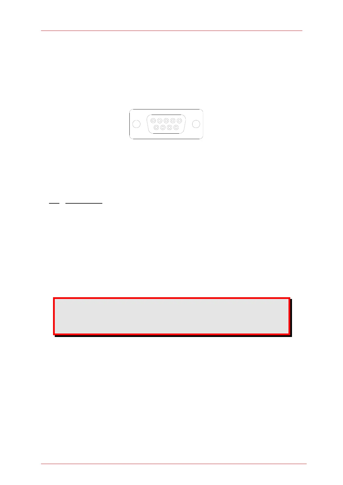
5-4-3-2-1
9-8-7-6
Figure 12 Pin assignment of the sensor connector jack(s) (female)
pin connection
3 photodiode ground (anode), thermal and pyro sensor ground, analog ground
4 photodiode cathode
5 pyro-electric sensor +
8 thermal sensor +
7 PRESENT connect this pin via a 1kΩ – 10kΩ resistor to Pin 3 (AGND)
1 +5V drive max. 50mA from this pin
6 DGND
9 n.c.
The following described pin is uniquely used for the memory in the sensor
head and may not be used. Connecting this pin may cause malfunction of
the PM100D.
2 EEPROM Digital I/O
69