DANGER:
With the exception of an individual being in full control of robot motion during hand-guiding,
personnel shall be outside the safeguarded space when the robot is in motion while in manual
mode (i.e.teaching).
The emergency stop on the robot stick shall be readily accessible during manual mode. At
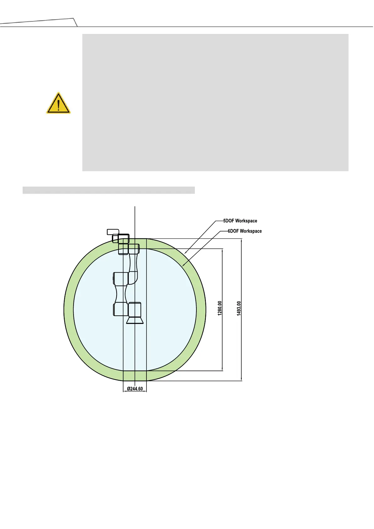
least one emergency switch is installed outside of the motion range of the robot. When no
motion limit is set for the robot, the motion range of the robot is equal to the maximum motion
range of the robot arm. You can set a motion limit to avoid the situation whereby all operations
have to be out of the maximum motion range of the robot arm.
The robot stick should be placed in an area that the robot cannot reach. The user should also
make sure that the movement of the robot will not be within any area where personnel will
enter to press any buttons on the robot stick.