Regular Payload Series-Hardware Installation Manual TM5 Series Hardware Version:3.1 Document Version:1.01 61
• Main fuse
• Residual current device (RCD)
It is recommended to install a master switch on the equipment power supply for robot applications for
servicing and inspection.
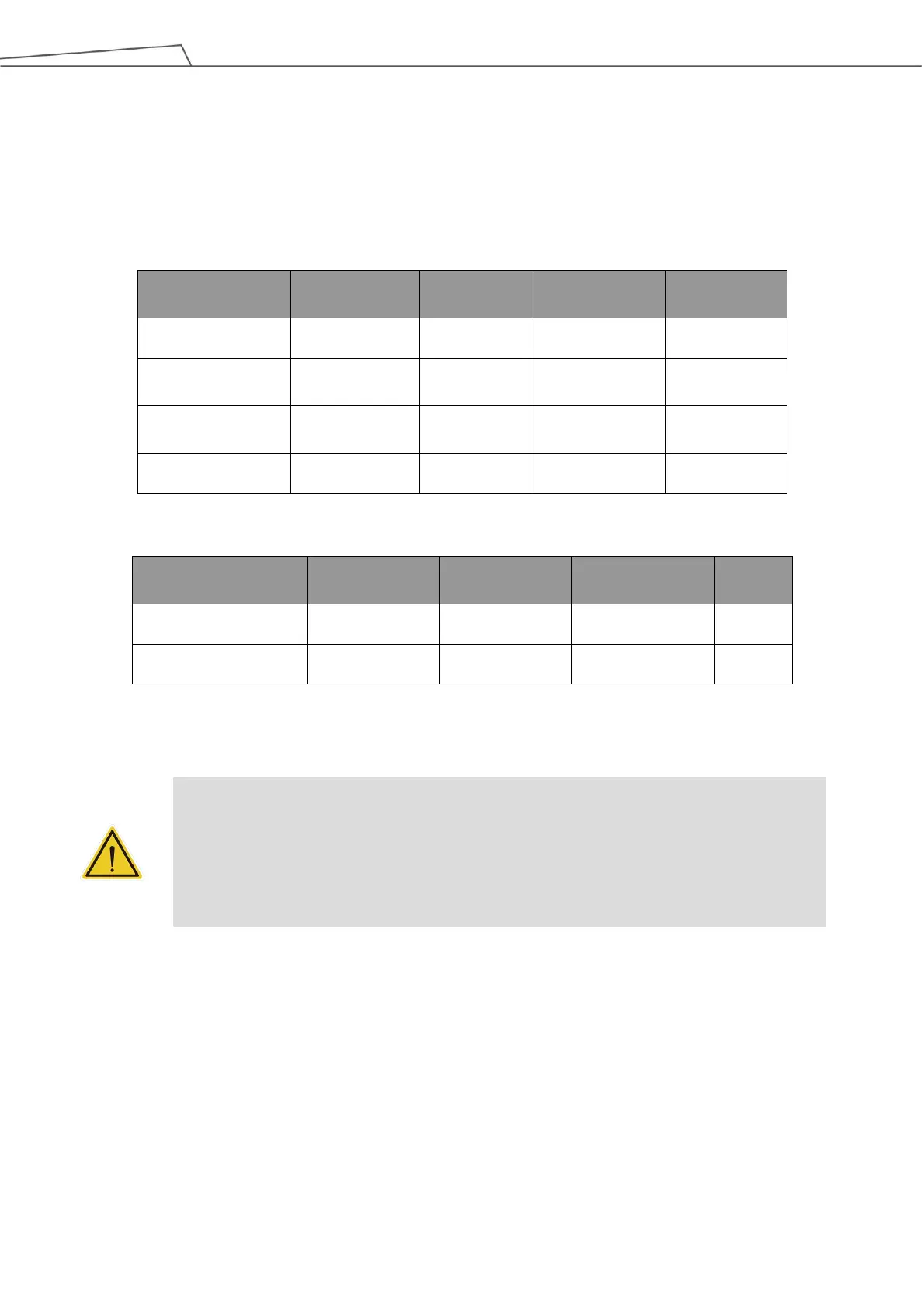
External mains fuse
(100V~120V)
External mains fuse
(220V~240V)
Table 12: TM5-700 / TM5-900 / TM5X-700 / TM5X-900 Electrical Specifications
Table 13: TM5M-700/ TM5M-900 Series Electrical Specifications
*If using DC22~47V power supply, the Robot will automatically limit the total output power
DANGER:
1. Ensure that the robot is correctly grounded (electrical grounding).
2. Ensure that the input current of the control box is protected by the Residual Current Device
(RCD) and appropriate fuses.
3. Ensure that all cables are correctly connected before the control box is energized. Always
use genuine power cables correctly.
5.6.2 Robot Interface
The following figure shows the connection interface of the robot. The cables of the robot are connected to
the control box through the interface.