EasyManua.ls Logo

TM Robot Regular Payload Series - Connecting Tool End Digital Output; Table 10: 5-Pin Analog I;O Connector of Cable; Table 11: 5-Pin Analog I;O Connector of Robot; Figure 47: Connecting Tool End Digital Output

Default Icon
81 pages
Print Icon
To Next Page IconTo Next Page
To Previous Page IconTo Previous Page
Loading...
Regular Payload Series-Hardware Installation Manual TM5 Series Hardware Version:3.1 Document Version:1.01 56
Pin
Wire Color
Pin Define
1
Black
+24V
24V output
2
Brown
DI_3
Digital Input3
3
Red
DO_3
Digital Output3
4
Orange
AI Analog
Input
5
Yellow
+0V
GND
Table 10: 5-pin Analog I/O Connector of Cable
Pin
Wire Color
Pin Define
1
Black
+24V
24V output
2
Brown
DI_3
Digital Input3
3
Red
DO_3
Digital Output3
4
Orange
AI Analog
Input
5
Yellow
+0V
GND
Table 11: 5-pin Analog I/O connector of Robot
5.4.2 Connecting Tool End Digital Output
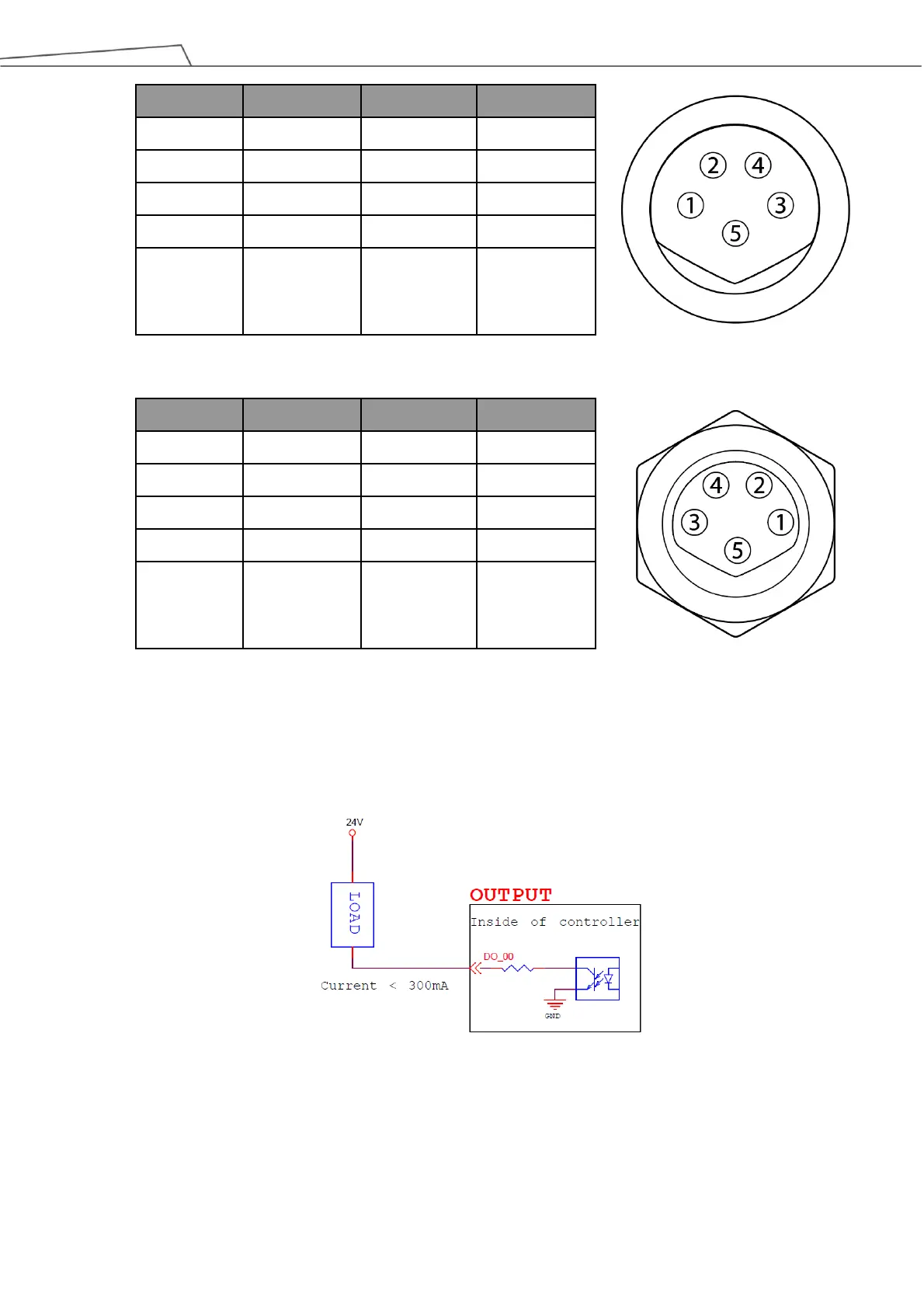
The following figure shows how to connect the tool end digital output:
Figure 47: Connecting Tool End Digital Output

Table of Contents

Related product manuals