Regular Payload Series-Hardware Installation Manual TM5 Series Hardware Version:3.1 Document Version:1.01 47
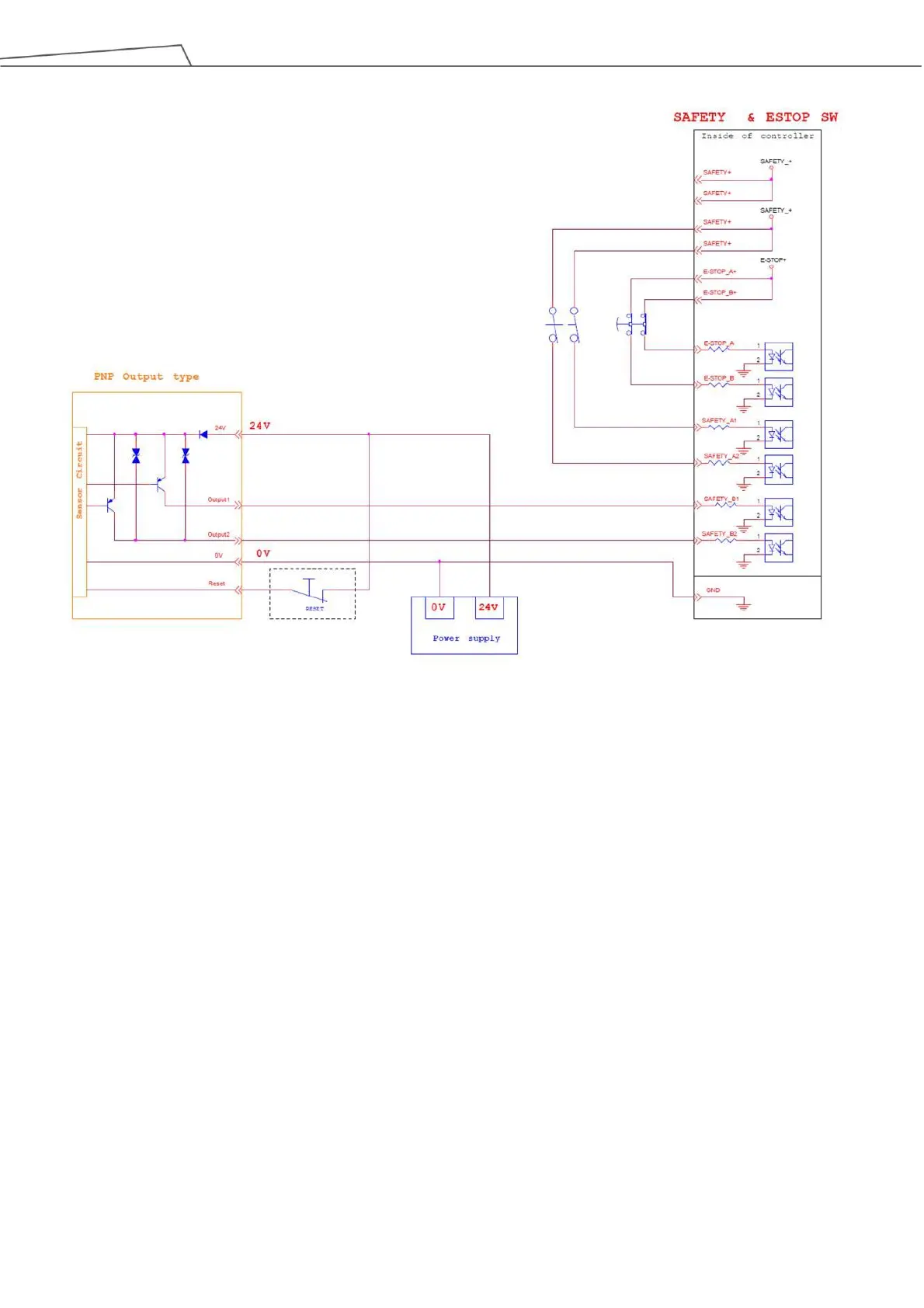
Figure 36: The Wiring Diagram Example of PNP Output Type Safety Device
5.3.2 Power Connector
1. During boot, the control box will check for an external 24V input. If none is found, then it will switch to
the internal 24V supply.
2. The control box itself offers a 24V1.5A output (24_EX). If the 24V load exceeds 1.5A, it enters Safe
Mode and disables the 24V output.
3. EX24V provides an external 24V input port. If the load exceeds 1.5A an external power supply can be
used instead. The load on EX24V must not exceed 3.5A.