71
18. MAINTENANCE FUNCTION
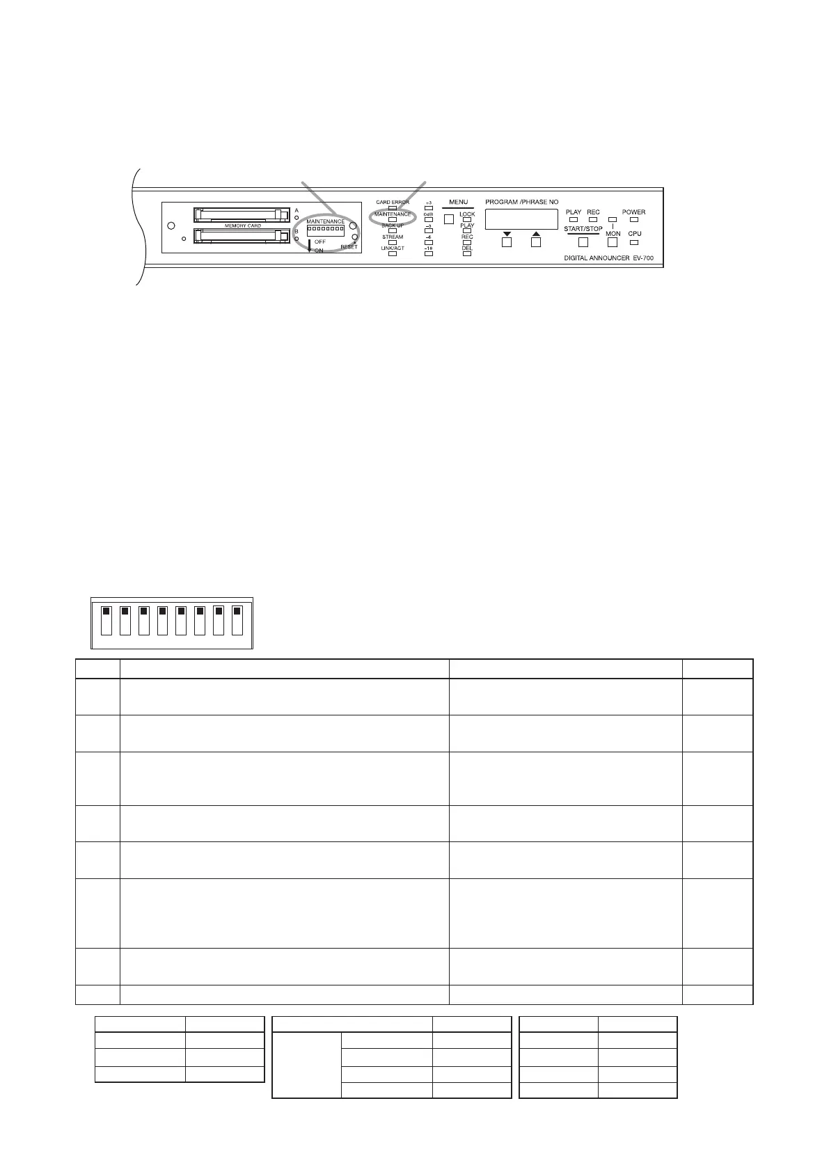
When any one of the switches of the DIP switch for Maintenance located inside the unit's front-mounted cover
is set to the ON position*
1
, the unit is placed in Maintenance mode, enabling the memory card backup and the
maintenance such as initialization of the unit settings.
The Maintenance indicator will ash when the unit is placed in Maintenance mode.
DIP switch for maintenance Maintenance indicator
Notes
• When in Maintenance mode, operation by way of contact activation and using the EV-700 Setting software
cannot be made.*
2
When maintenance is complete, be sure to return all the switches of the DIP switch for
maintenance to the OFF position.
*
2
When only Switch 3 is set to the ON position, network setting using the EV-700 Setting software is available.
• Using the EV-700 Setting software, it is also possible to place the unit in Maintenance mode to perform
maintenance.
If any of the switches is set to the ON position, broadcast by way of contact control or using the EV-700
Setting software may not be activated. Be sure to return the switch to the OFF position when you nish work.
[Function of the DIP switch for maintenance]
The table below shows functions of each DIP switch for maintenance.
If a corresponding switch is set to the ON position, the unit is placed in Maintenance mode.
When you nish work in Maintenance mode, return the DIP switch to the OFF position.
If any one of the switches is set to the ON position, broadcast by way of contact control or using the EV-700
Setting software cannot be made.
1 2 3 4 5 6 7 8
Switch
Function
Indication on the Status display
Ref. page
1 Used to play all programs and also adjust whole
sound volume.
PG.VoL p. 72
2 Used to play, record, or delete Emergency playback
audio source.
EMEr p. 52
3 Used to upload or download the setting les between
the unit and memory card and also return the network
setting to the default values*
3
temporarily.
Download : SEtdL
Upload : SEtdL
p. 74
4 Used to copy les on the memory card A to the
memory card B.
CFCPy p. 75
5 When set to the ON position along with Switch 8, the
rmware recorded on the memory card is updated.
Displays the current rmware version
number.
p. 76
6 When set to the ON position along with Switch 8, the
unit setting is initialized.
Displays the target to initialize.
Settings other than the network: unit
Only network setting: nEt
All settings: ALL
p. 77
7 When set to the ON position along with Switch 8,
Self-check will be executed.
During Self-check: tESt.
History storage memory error: Err51
p. 78
8 Use this switch in conjunction with Switch 5 or 6. −
p. 76, 77
*
3
Setting item Default value Setting item Default value Setting item Default value
IP address 192.16 8.14.1 Port number HTTP 8080 User name EV700
Subnet mask 255.255.255.0 FTP control port 21 Password guest
Default gateway 0.0.0.0 FTP data port 60020 Device name EV-700
Device control 60007 System name EV-700
*
1
When both Switches 7 and 8 are set to the ON position, the unit will not enter Maintenance mode.