44
OPTIONAL OPERATIONS
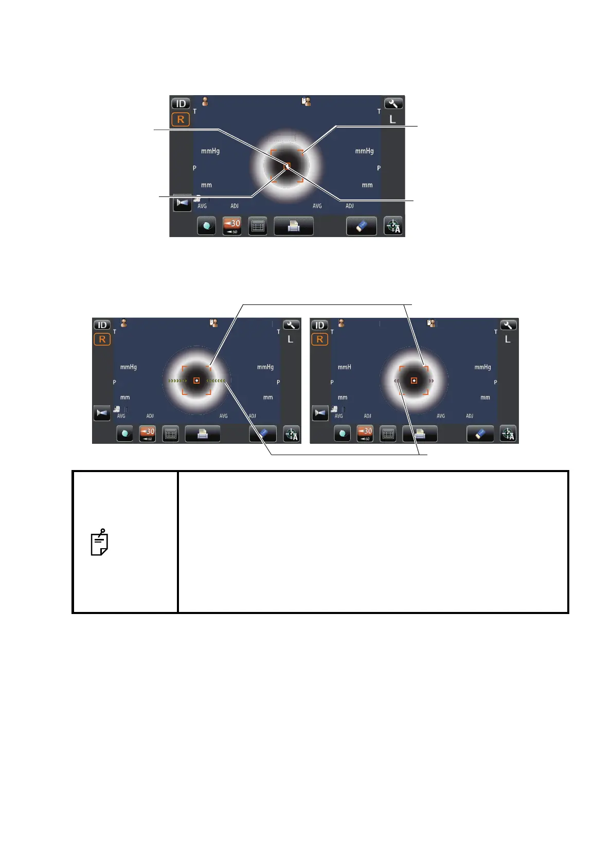
4 While moving the main body toward the patient, focus the target eye.
A vague, reflected alignment dot appears on the cornea.
5 When the main body is brought closer to the patient's eye, Z alignment arrows appear on the
control panel screen.
NOTE
• Do not allow the eyelash and eyelid to cover the outer alignment mark to
ensure stable measurement.
• If the machine is too close to the patient's eye in comparison with the opti-
mal alignment position, outward magenta-colored Z alignment arrows
blink with a message "TOO CLOSE," or if it is too far the arrows are
changed to inward lime green color, and if the machine is completely off
the alignment range, the message "TOO FAR" is displayed." The number
of arrows are reduced accordingly as the optimal alignment reference
position comes closer. If the alignment reaches the measuring range, the
arrow is displayed in aqua color.
12.0012.00
0101
VDVD
00001000010000000100001000 0000100001000
mmmm
R
S
C
A
K
R1
R1
R2R2
A1A1
R
S
C
A
K
R1
R1
R2R2
A1A1
ID
LR
0/30/3 0/30/3
0/30/3 0/30/3
R/KR/K
KRTKRT
REFREF
P
tientI
OPCON
AROU
Outer alignment mark
Alignment mark
Alignment dot
Alignment area
P
tientI
OPCON
AROU
12.0012.00
0101
VDV D
ID
LR
0/30/3 0/30/3
0/30/3 0/30/3
R/KR/K
KRTKRT
REFREF
P
tientI
PC
N
AR
U
Outer alignment mark
Z alignment arrows