20
COMPONENTS
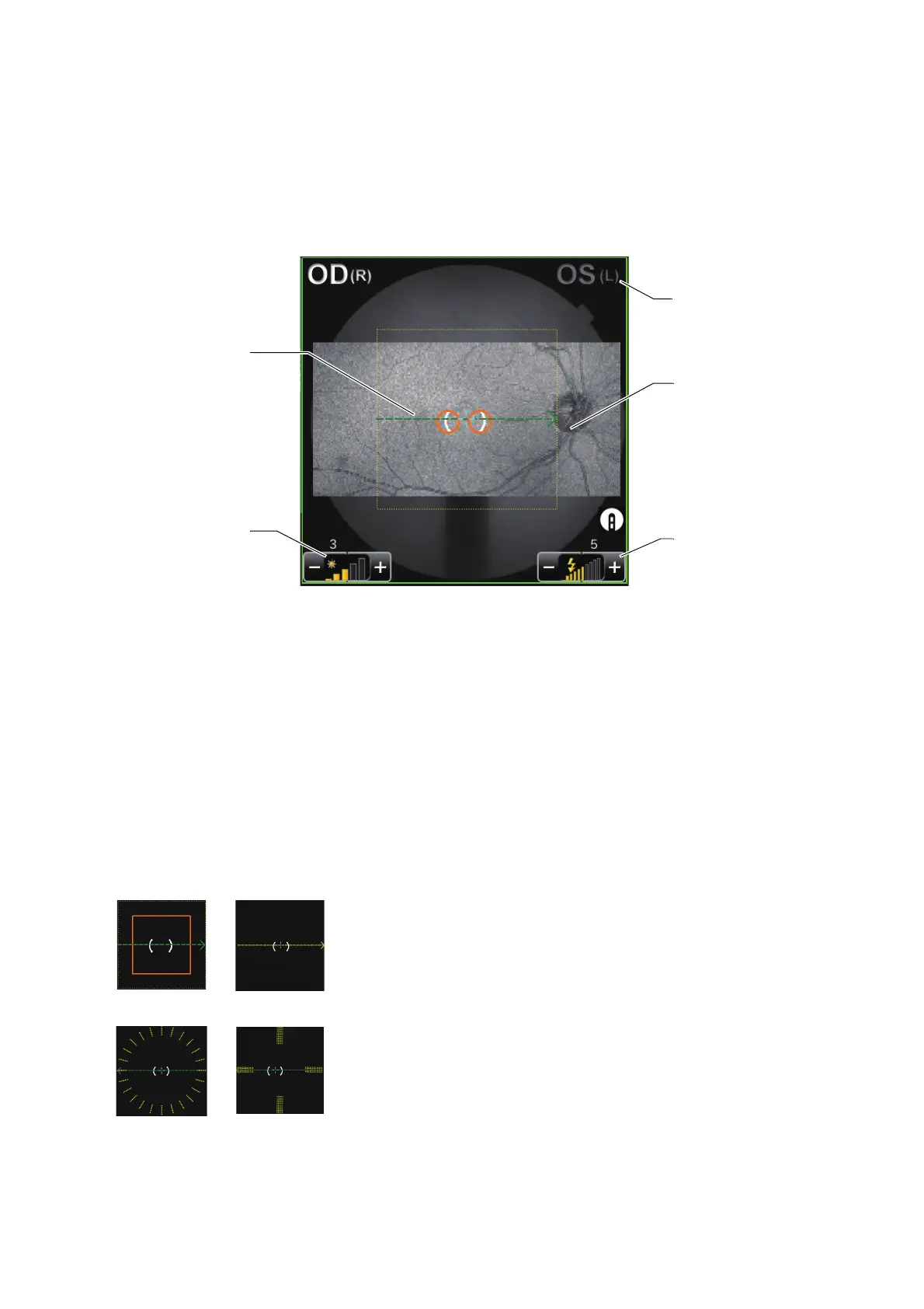
Fundus/anterior segment live image area
This area displays the fundus live image, the right/left eye, illumination level and besides, the graphic
image of the scan pattern, which is set on the selected capture icon, with an interrupted line. You can
set ON/OFF of the illumination level by the touch display. In the scan position adjustment mode, the
interrupted line of the scan pattern display is changed to the solid line display. The scan position
adjustment range and fine adjustment buttons are displayed. You can adjust the scan position by the
touch display.
• Live image:
Displays the fundus live image.
• Scan pattern display (green and yellow):
Displays the graphic image of the scan pattern, which is set on the selected capture icon. The
green line shows the scan position, and the arrow shows the scan advance direction. (The arrow
direction for the right eye is reversed for the left eye.)
The yellow line is displayed for the scan pattern except "Line". For "3D", the yellow line shows the
scan range and, for other scan patterns, the scan position in addition to the position indicated by the
green line. When scan is performed once, it is done at the positions indicated by the green and yel-
low lines.
The length and size of the lines are changed according to the set value of scan size.
• Right/left eye display:
Right/left eye
display
Live image
Flash level
display
Scan pattern display
(green and yellow)
* Dotted line
Illumination
level display
3D (H) Line
5 Line CrossRadial
 Loading...