Afoursectiongearpumpiscoupledtothepiston(traction)pump.Thethirdgear
pumpsectionsupplieshydraulicowtoboththeliftcontrolmanifoldandthe
steeringcontrolvalve.Hydraulicowfromthispumpsectionisdeliveredtothe
circuitsthroughaproportionalowdividerlocatedinthefancontrolmanifold.
Maximumlift/lowercircuitpressureislimitedto110bar(1600PSI)byarelief
valve(R1)intheliftcontrolmanifold.Liftcircuitpressurecanbemonitoredatlift
controlmanifoldtestttingG1.
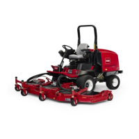
TheGroundsmaster4700-Dhasthree(3)liftswitchestocontrolthecutting
decks(Figure41).Thecenterswitchisfortheve(5)centerdecks,theleft
switchcontrolstheleft,reardeck(#6)andtherightswitchcontrolstheright,rear
deck(#7)(Figure42).
Whenthecuttingdecksareinastationaryposition(notraisingorlowering),lift
circuitowfromthethirdpumpsectionbypassestheliftcylindersthroughthe
liftcontrolmanifoldsolenoidvalveS1andproportionalreliefvalveTSwhich
arede-energized.Returnowfromthemanifoldisroutedtotheoillterand
tractionchargecircuit.
Note:Theoperatormustbeintheoperatorseatinordertolowerthecutting
decks.
g308049
Figure41
1.Liftswitch(#1to#5)3.Liftswitch(#7)
2.Liftswitch(#6)
g308050
Figure42
GM4700-DCuttingDeckLocations
CuttingDeckLower
Tolowerthecenterve(5)cuttingdecksonaGroundsmaster4700-D,thefront
ofthecenterliftswitchisdepressed.TheswitchactsasaninputtotheTEC
controller(T1)whichthenprovidesanelectricaloutputtosolenoidvalvesS1and
S6intheliftcontrolmanifold.Theseenergizedsolenoidvalvesshifttoallowoil
HydraulicSystem:HydraulicFlowDiagrams
Page5–24
Groundsmaster
®
4500-D/4700-D
19245SLRevA

 Loading...


