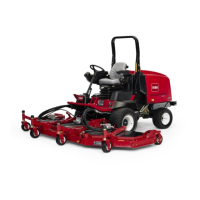
Removal(Figure148)(continued)
g309018
Figure149
1.Manifoldbody4.Straighttting(3used)
2.Orice(0.055)
5.Zeroleakplug
3.Orice(0.030)
g309019
Figure150
1.Manifoldbody4.O-ring
2.O-ring5.90ºhydraulictting
3.Straighttting(3used)
5.RemovehydraulicmanifoldfromtheframeusingFigure148asguide.
IMPORTANT
Aowcontroloriceisplacedbeneathseveralofthehydraulic
ttingsontheliftcircuitjunctionmanifold(Figure149).Themanifold
usestwo(2)differentoricesizes.Ifattingisremovedfromthelift
junctionmanifoldandanoriceisinthemanifoldport,makesureto
removeoriceandlabelitspositionforassemblypurposes.Also
notelocationofgrooveinoriceforassemblypurposes.
HydraulicSystem:ServiceandRepairs
Page5–164
Groundsmaster
®
4500-D/4700-D
19245SLRevA

 Loading...


