Removal(Figure285)(continued)
#4 Deck #1 Deck #5 Deck
#7 Deck
(GM4700)
#6 Deck
(GM4700)
#3
Deck
#2
Deck
g308386
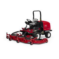
Figure286
CUTTINGDECKLOCATIONS
3.Ifliftarmforeitherdeck#4or#5(Figure286)istoberemoved,clean,label
andremovehydraulichosesfromthedeckmotor(Figure287).Placeplugs
orcapsonopenttingsandhoses.Slidehosesoutofthehoseretaining
loopontheliftarm.
4.Removeliftcylinderpin(item4)thatsecureshydraulicliftcylindertoliftarm.
5.Loosenandremovelocknut(item11)fromliftarmpivotpin.
6.Supportliftarmandpullliftarmpivotpinfromliftarmandframe.Locateand
removethrustwashersfrombothsidesofliftarmduringpivotpinremoval.
7.Removeliftarmfrommachine.
8.DisassembleliftarmasneededusingFigure285asaguide.
9.Cleanliftarmandpivotpin.Inspectliftarmbushingsandpivotpinfor
damageorwear.Replacewornordamagedcomponents.
Installation(Figure285)
1.AssembleliftarmusingFigure285asaguide.
2.Positionliftarmtoframe.Fitthrustwasher(item10)betweenbothsidesof
liftarmandframe.Slidepivotpinintoframeandliftarm.Alignrollpinin
pivotpinwithslotinframeange.
3.Installandtightenlocknut(item11)tosecureliftarmpivotpin.
4.Installhydraulicliftcylindertoliftarmwithcylinderpin.Securecylinderpin
toliftarmwithangeheadscrewandangenut.
Note:Installthrustwasher(item33)oncarrierpivotshaftbeforeinstalling
cuttingdeckonpivotshaft.
5.Positionandinstallcuttingdecktoliftarm(seeCuttingDeckOperator’s
Manual).
Groundsmaster
®
4500-D/4700-D
Page8–13
Chassis:ServiceandRepairs
19245SLRevA

 Loading...


