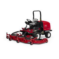
g310581
Figure299
1.Socketheadscrew
2.Hydraulicmotor
Removal(Figure298)
1.Parkmachineonalevelsurface,lowercuttingdecks,stopengine,engage
parkingbrakeandremovekeyfromtheignitionswitch.
2.Removetwo(2)socketheadscrewsandatwashersthatsecurehydraulic
motortothecuttingdeck(Figure299).RemovehydraulicmotorandO-ring
fromdeck.
3.Covertopofspindletopreventdebrisfromenteringspindle.Aspindleplug
(seeSpecialT ools(page2–16))canbeusedtocoverspindle.
Note:Ifdesired,cuttingdeckcanberemovedfrommachineforspindle
removalfromcuttingdeck.
4.Ifspindleistoberemovedwithcuttingdeckattachedtothemachine,start
theengineandraisethecuttingdeck.Stopengineandremovekeyfromthe
ignitionswitch.Supportthecuttingdecksoitcannotfallaccidentally.
5.Removebladebolt,anti-scalpcupandcuttingblade.
6.Removeangenutsthatsecurespindleassemblytocuttingdeck.Slide
spindleassemblyoutthebottomofthedeck.Removespindleplatefrom
topofdeck.
7.Ifnecessary,pressdrivestuds(item7)fromspindleassembly.
Installation(Figure298)
1.Ifdrivestuds(item7)wereremovedfromspindleassembly,pressnewdrive
studsintospindle.Makesurethatstudheadsarefullypressedagainst
spindlesurface.
2.Positionspindleassemblyandspindleplatetocuttingdeck.Notcheson
cuttingdeckandspindleplateshouldbealignedtofrontofdeck.
3.Securespindleassemblyandspindleplatetocuttingdeckwithangenuts.
Tightenangenutsinastarpattern.
4.Installcuttingblade,anti-scalpcupandbolt.Tightenbladeboltfrom120to
146N·m(88to108ft-lb).
5.Removecoverfromtopofspindlethatwasplacedtopreventdebrisfrom
enteringspindle.
Groundsmaster
®
4500-D/4700-D
Page9–5
CuttingDecks:ServiceandRepairs
19245SLRevA

 Loading...


