

A
Adam OlsenAug 2, 2025
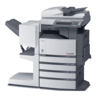
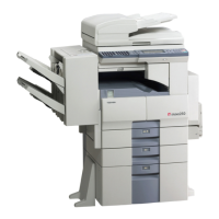
What to do if my Toshiba All in One Printer images are blurred?
- SsaraclarkeAug 2, 2025
If your copy images are blurred, ensure the original is placed firmly on the glass and the cover is closed properly. If the problem persists, try replacing the paper with new paper.