EasyManuals Logo

Toshiba TOSVERT VF-nC3 User Manual

Toshiba TOSVERT VF-nC3
254 pages
To Next Page IconTo Next Page
To Previous Page IconTo Previous Page
Page #178 background imageLoading...
Page #178 background image
E6581595
G-3
7
Connecting
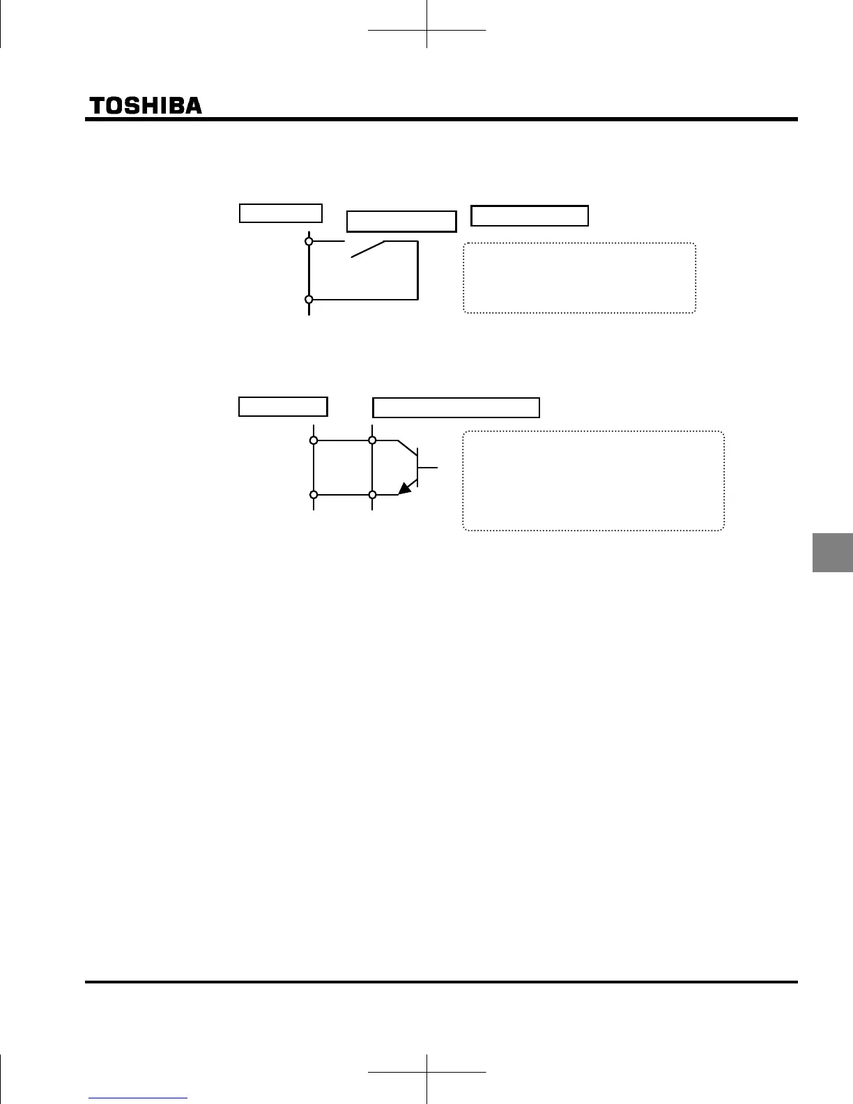
1) For logic input a
2) For connection (sink logic) via transistor output
About programmable controllers and interfaces
Supply the power for logic input terminal from external to P24 terminal (external 24Vdc input terminal) in case of
controlling the inverter by using an open collector output of programmable controller.
CC
Input terminal
Operates by short circuiting between
the input terminal and CC (common).
Use for forward rotation, reverse
rotation, and multi-stage speed.
Inverte
r
Relay a-contac
t
With sink settings
Control by connecting the input terminal
and CC (common) to the output (non-logic
switch) of the programmable controller. Use
for forward rotation, reverse rotation, and
multi-stage speed. Use a 5 mA transistor
that operates at 24 V dc.
Inverte
r
Programmable controller
CC
Input terminal

Table of Contents

Other manuals for Toshiba TOSVERT VF-nC3

Questions and Answers:

Question and Answer IconNeed help?

Do you have a question about the Toshiba TOSVERT VF-nC3 and is the answer not in the manual?

Toshiba TOSVERT VF-nC3 Specifications

General IconGeneral
ModelVF-nC3
CategoryInverter
Output Frequency Range0.1 to 400 Hz
Control MethodV/f control, sensorless vector control
Overload Capacity150% for 60 seconds
Input Frequency50/60 Hz
Enclosure RatingIP20
Input Voltage200-240V AC
Protection FeaturesOvercurrent, Overvoltage, Undervoltage, Overheat, Short Circuit
Ambient Temperature-10°C to +50°C
CommunicationModbus RTU
Cooling MethodFan Cooled
Operating Temperature-10°C to +50°C
Storage Temperature-20°C to +60°C
Humidity5 to 95% RH (non-condensing)
AltitudeUp to 1000m
Braking UnitBuilt-in braking transistor (for models up to 22kW), External braking resistor required

Related product manuals