E6581595
I-7
9
9.2.3 Compliance with Connection
Use the UL conformed cables (Rating 75 °C or more, Use the copper conductors only.) to the main circuit
terminals (R/L1, S/L2, S/L2/N, T/L3, U/T1, V/T2, W/T3).
For instruction in the United States, Integral solid state short circuit protection does not provide branch circuit
protection. Branch circuit protection must be provided in accordance with the National Electrical Code and any
additional local codes.
For instruction in the Canada, Integral solid state short circuit protection does not provide branch circuit protection.
Branch circuit protection must be provided in accordance with the Canadian Electrical Code and any additional
local codes.
-> For recommended tightening torque for the main terminal, refer to section 1.3.3.
-> Use the ring terminal for the earth cables except grounding terminal on power supply terminal block, see Table 1.
-> For recommended wire size for the main terminal, see Table 2.
->Use the electric wire of Class 1 for the control wire. (For wire size and tightening torque, see the label on unit)
Table 1 Ring terminal sizes for earth cables
Earth Cable Sizes M4 (grounding terminal) M5 (grounding terminal)
AWG14 R2-4 [JIS standard] R2-5 [JIS standard]
AWG12 R5.5-4 [JIS standard] R5.5-5 [JIS standard]
AWG10 R5.5-4 [JIS standard] R5.5-5 [JIS standard]
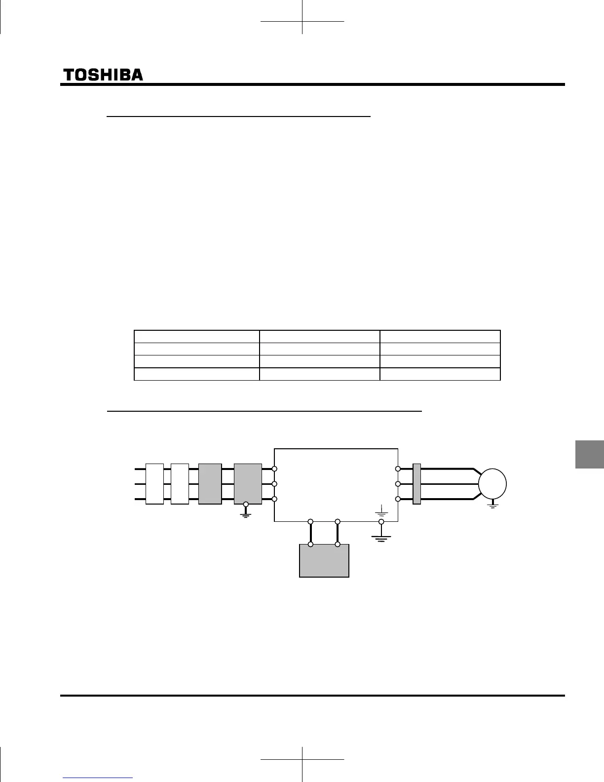
9.2.4 Compliance with Peripheral devices
Connections with peripheral equipment
*1: The T/L3 terminal is not provided for any single-phase class.
So if you are using single-phase class, use the R/L1 and S/L2/N terminals to connect power cables.
*2: Use the UL listed fuses at connecting to power supply.
Short circuit test is performed under the condition of the power supply short-circuit currents.
These interrupting capacities and fuse rating currents depend on the applicable motor capacities.
For input withstand rating, fuse rating currents and wire size, see Table 2.
o
o
Power
supply
nver
e
DC reacto
Fuse
*2
R
L1
S
L2
T
L3
*1
P0
/+
V
T2
U
T1
W
T3
IM
Magnetic
contactor
Input AC
reactor
Noise
reduction filter
Zero-phase
reactor

 Loading...


