2-3 Descriptions of Terminal and Wiring Diagram
2-3-1 Wiring Diagram
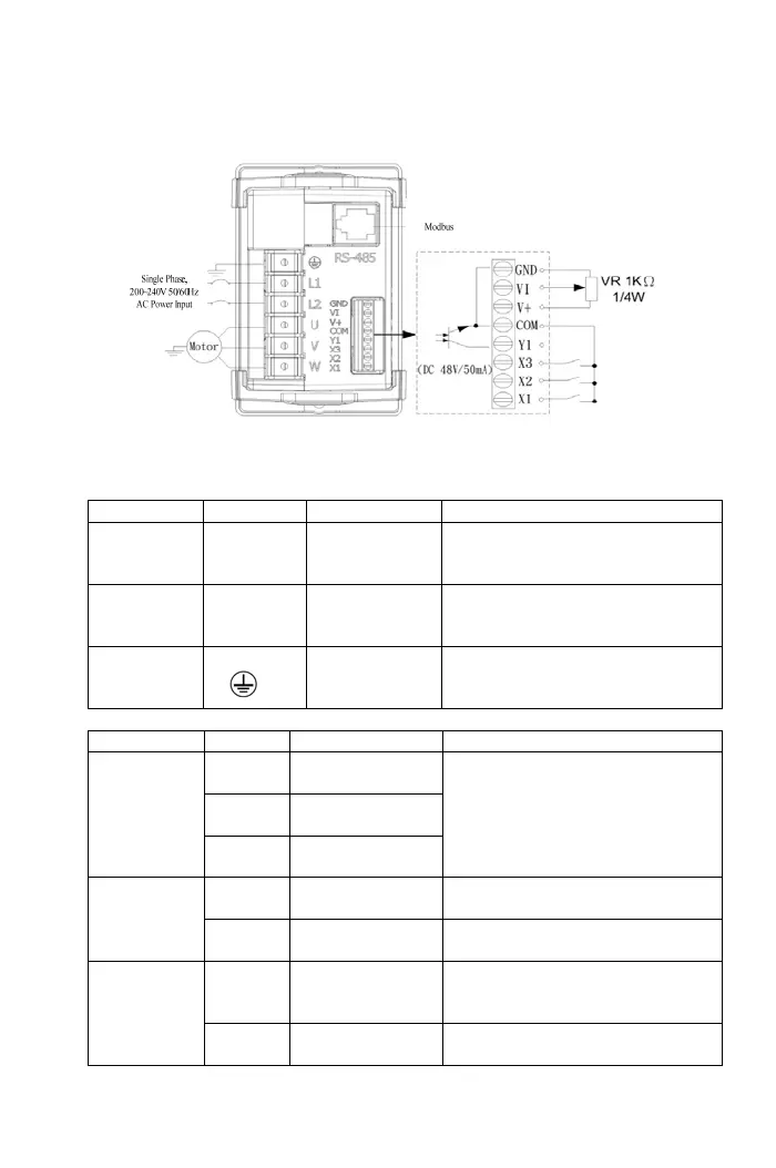
2-3-2 Wiring Diagram
a. Main Circuit Connection
Type Symbol Function Description
Power
Source
L1,L2
AC power
source input
terminals
Single-phase; sinusoidal power
source input terminal.(200~240V)
Motor U,V,W
Drive outputs to
motor terminals
The terminals output three phase
variable frequency and voltage to
motor.
Grounding
Grounding
terminal
Ground the drive in compliance
with the NEC standard or local
electrical code.
b. Control Terminals
Type Symbol Function Description
X1
Multi-function
input terminal 1
X2
Multi-function
input terminal 2
Input
terminals
X3
Multi-function
input terminal 3
Short the terminal with COM and
set the function F5.19~F5.21.
Y1
Multi-function
output terminal 1
Short the terminal with COM and
set the function F5.26
Output
terminals
COM
Input/output
common terminal
The common terminal of input
control signal.
V+
Power terminal for
analog input
control
12V position: Maximum supplied
current is 20mA.
Control power
VI
Analog signal
input terminal
DC 0~10V
11