Chapter 6 Communication Description
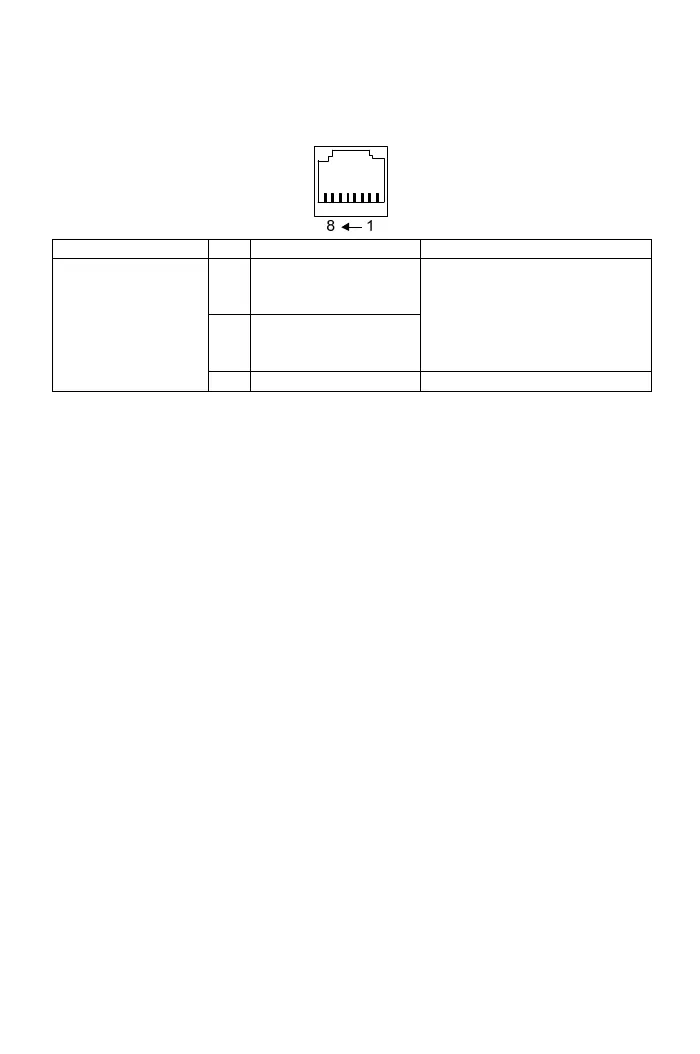
6-1 Modbus Port (RJ-45)
Type Pin Function Description
1
Communication
transmission terminal
(DX+)
2
Communication
transmission terminal
(DX-)
Differential input of RS-485
*Note 1
Modbus (RS-485)
communication only uses pin1,
2.
Modbus(RS-485)
communication
3-8 Reserved Reserved
Note 1: The terminal resistor(100Ω) selection is set by DSW1(Default setting: ON)
Note 2: When using multiple sets of drive, connect all the DX+, DX- terminals of each drive by
series, and connect the shielded net of the connection wire to FG terminal.
Note 3: The function of terminal resistor is to terminate the electric signal and avoid the reflective
signal to interfere the signal. Switch DSW1 to “ON” position of the first and last drive and
switch to “1” position for other drives. The default value is “ON” position.
Note 4: The cable length from the controllers(PC, PLC) to the last drive cannot exceed 500m.
Note 5: Max. controller number are 31 sets.
81