Chapter 5 Parameter Setting Description
F0 System Parameters
【F0.00】 Drive Information
a. The function can display the horse power and software version. Check if the
capacity of drive corresponding to the drive by this function.
b. This manual and software version must be identical.
The drive with different software version cannot duplicate drive parameters, or
the drive operation panel will display Wr_F.
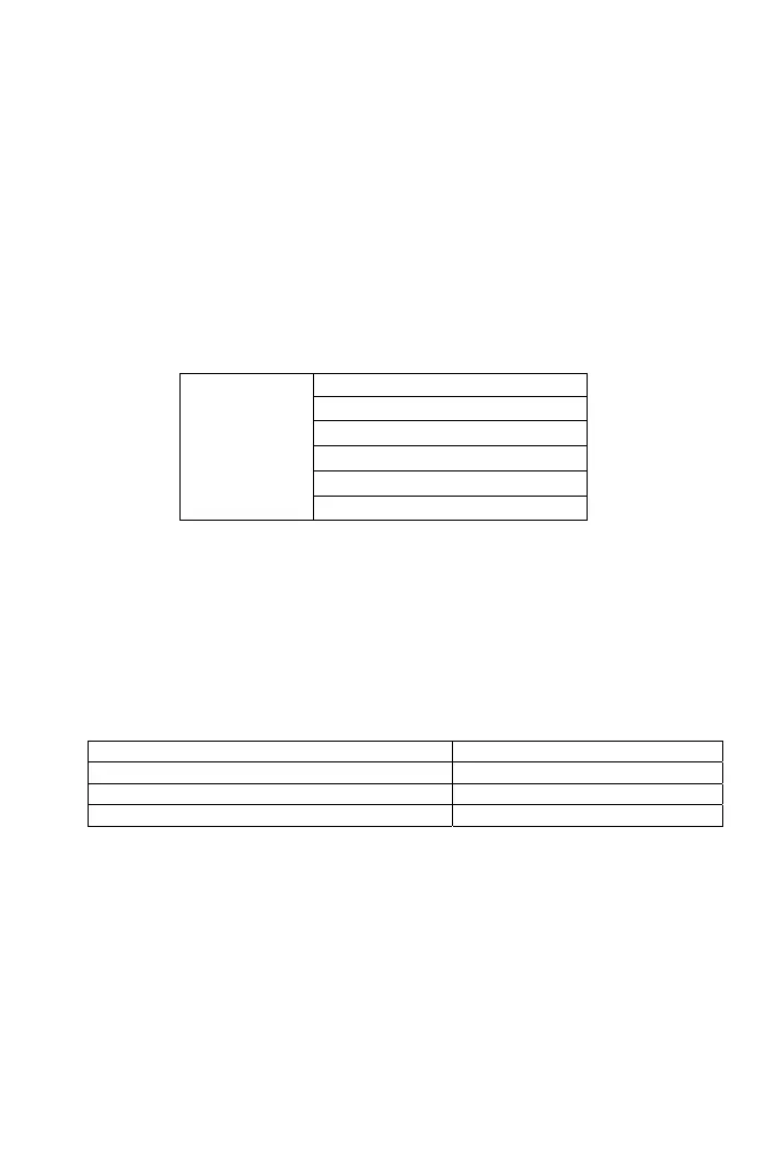
c. The descriptions of LED indicators shows the different displays of the operation
panel, and LED indicator displays are shown as below table.
d. The left 2th bits of drive model number for 200V single-phase series displays ”S”.
Hz V A
○ ○ ○
Software version
● ○ ○
Drive model number
○ ● ○
Drive rated current
● ● ○
Drive running hours
○ ○ ●
Drive supply power time(Hours)
● ○ ●
Software checksum code
【F0.01】 Parameter Lock
a. Protect the parameter settings to prevent parameter settings from unexpected
adjustments causing the system operated incorrectly.
b. The parameter setting as the following
0: Parameters are changeable
1: Parameters are not changeable
【F0.05】 Power Source
a. The power source setting as the following table
Power source specification Range
100V series 100.0~120.0V
200V series 190.0~240.0V
400V series 340.0~480.0V
b. The power source setting must be according to the actual power source and the
setting will affect the activation validity of LE, LE1 and the validity of V/F outputs.
【F0.08】 Fault Record 1
a. Record the latest 6 times of fault messages.
b. The fault messages selection are listed as the following:
0: Fault code
1: Output current at drive fault
2: DC bus voltage at drive fault
3: Output frequency at drive fault
38