68
TK 61753-2-MM-EN
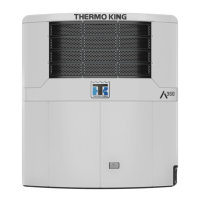
Figure 17. Component Layout - shown in high idle position (solenoid energized)
1. Engine Throttle
2. Throttle Linkage
3. Adjust throttle linkage so throttle touches HS stop screw
4. 2000 HS Stop Screw – Non-adjustable (set by Yanmar)
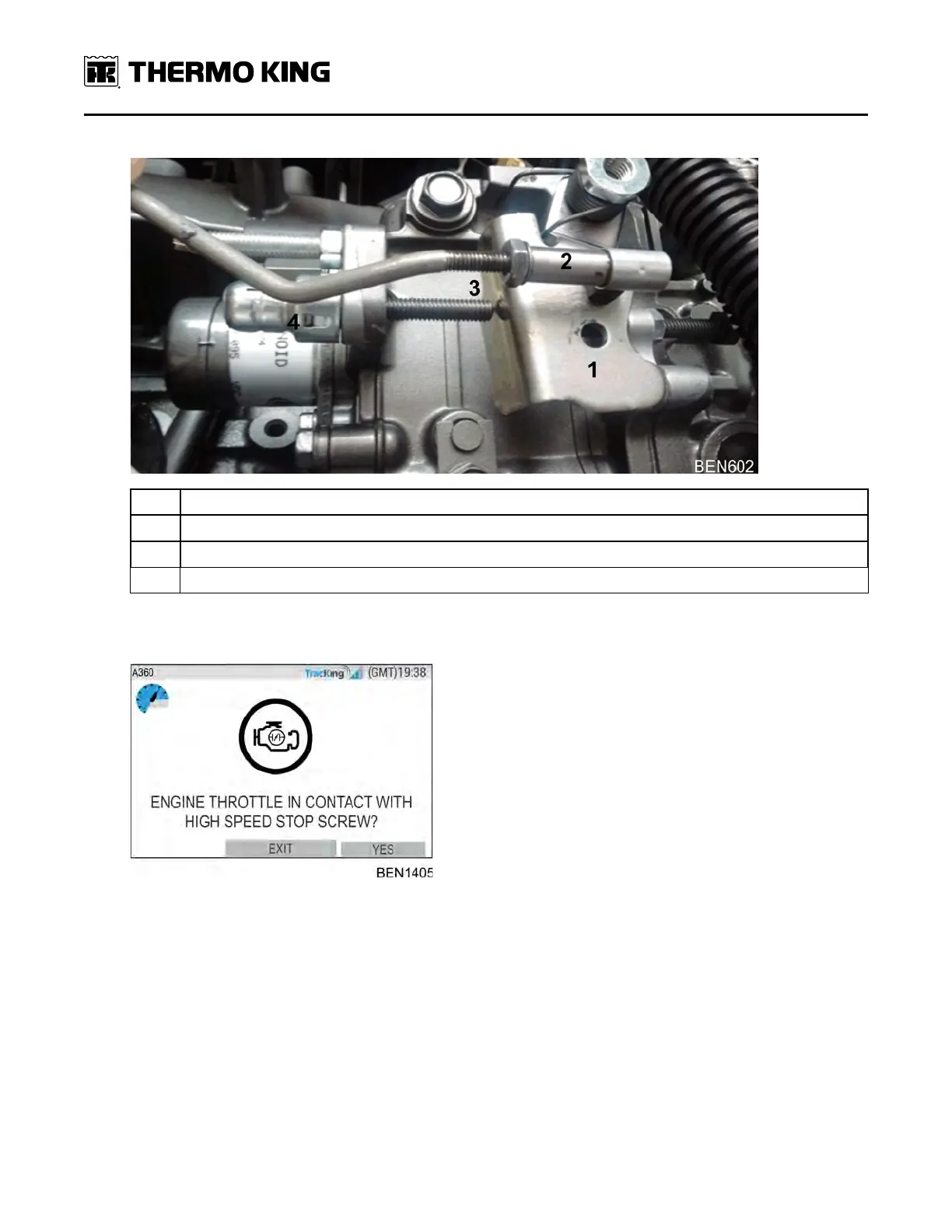
• For 1450 RPM high speed unit models: Engine throttle should be in contact with adjustable HS Stop Screw
• HMI shall request technician to confirm this before proceeding to the high and low calibration:
• Once confirmed via HMI, NRMM calibration shall begin.
• The controller shall determine which calibration actions to perform and what is the target RPM based on the
configured unit type via Guarded Access menu.
EEnnggiinnee MMaaiinntteennaannccee