70
TK 61753-2-MM-EN
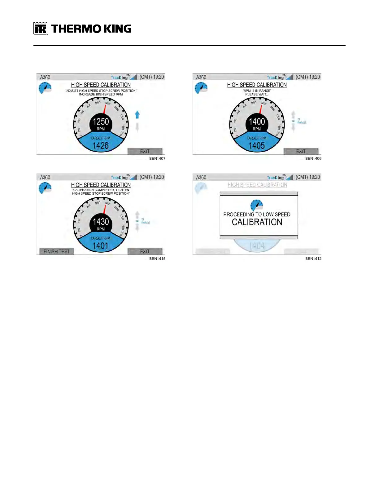
Table 4. High Speed Stop screw position adjustments
1. 2.
3. 4.
1. Adjust (slightly) the extra stop screw so that the engine speed target is within 10 RPM of the current engine speed
displayed on the HMI.
• This may be somewhat of an repetitive process
• RPM and Target RPM values should stabilize after 10-20 seconds
• The target RPM value will probably not be 1450
• The target RPM is determined by the load on the engine at the time of the test
When the engine speed target is within 10 RPM of the current engine speed for 10 consecutive seconds, the HMI will
display the option to finish test.
2. Tighten the high speed stop screw position to within 10 RPM.
• Verify via the HMI that the engine speed is still within the desired range after the set screw is locked down.
– This may be somewhat of an repetitive process.
• Once satisfied, Select via HMI to Finish Test.
• The HMI will then proceed to the low speed calibration test.
Low Speed Calibration
The Low Speed Calibration Procedure is similar for all unit models. The only difference is that the controller shall
determine (via unit configuration) the appropriate low speed RPM (either 1200 or 1250 RPM). Similar to the 1450 high
speed calibration, the low speed calibration is performed manually. The technician will be required to manually adjust
the low speed stop screw position in order to calibrate low speed setting.
EEnnggiinnee MMaaiinntteennaannccee