Operation
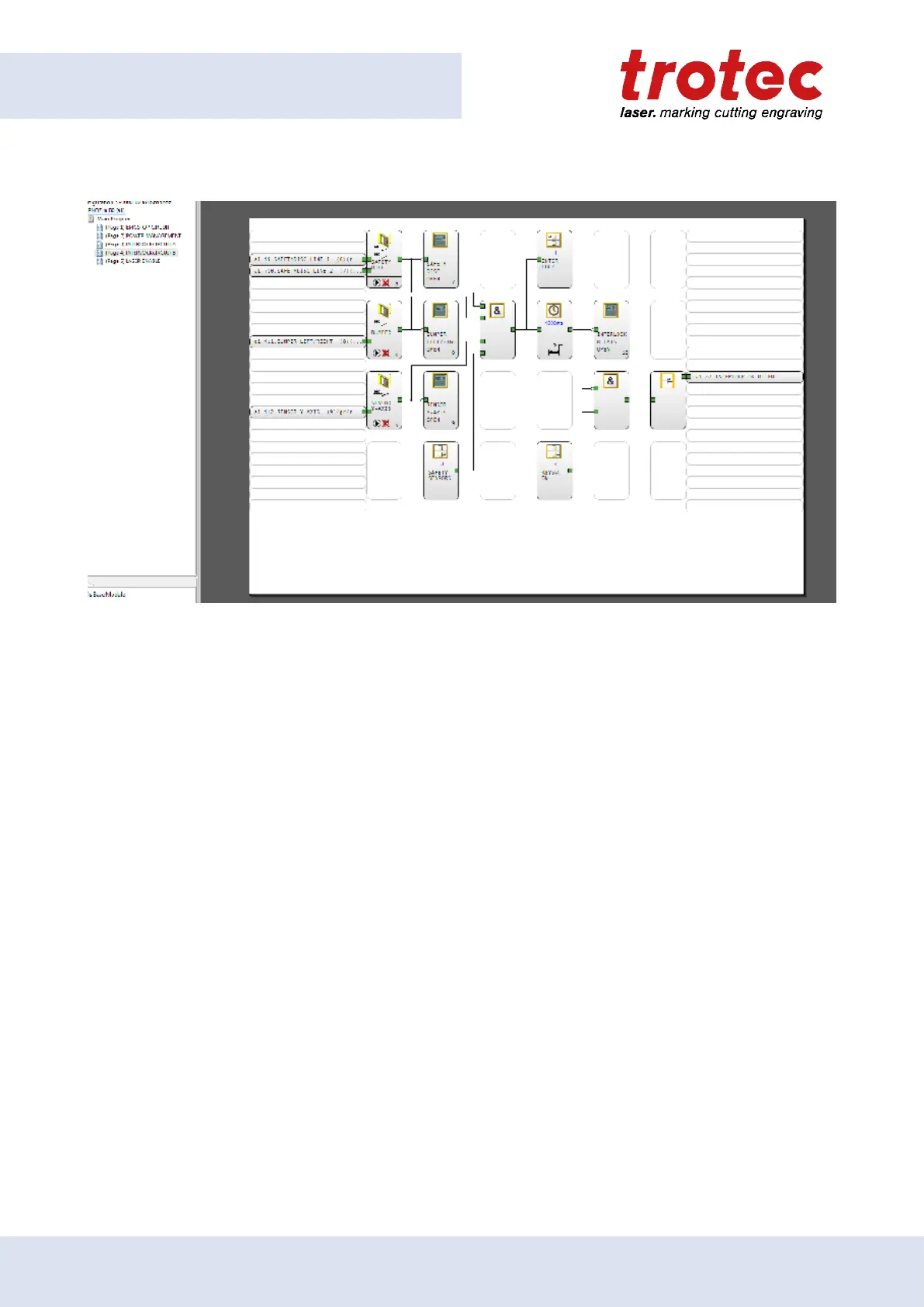
The remaining incoming sensor inputs can be controlled here. On the upper left, the safety monitor is
monitored in two directions. The input of the roller lever switches of both bumpers is shown below. Below
is the input of the infrared light barrier of the y-axis. The right output goes to the warning display on the
console. When all sensors are ok and closed, the output should no longer be set and the LED on the console
will go out. As an example, you can see from the upper picture that the two inputs of the safety device are
not active. Consequently the safety device is not mounted or defective.
Page 5: LASER ENABLE
Click on page 5 to see the LASER ENABLE circuit.
72 ENGLISH (Translation)