3.6 Compartment wall or safety wall with metal sup-
port structure, cladding on both sides
6.2 Mineral wool, ≥ 1000 °C, ≥ 80 kg/m³
6.5 Mineral wool (depending on wall construction)
6.11 Insulating strip (depending on wall construction)
7.1 UW section
7.3 UA section
7.5 Steel support structure
7.10 Trim panels *
7.11 Trim panels, fire-resistant, 2-ply, max. 25 mm
(alternative to 6.2 and 7.14)
7.23 Sheet steel insert depending on wall manufac-
turer
9.2 Extension piece or duct
Z Spigot construction 370 mm
Flange construction 342 mm
* The total thickness of the trim panels must not
exceed 25 mm
# optional
–
Up to EI 90 S
Up to EI 60S
–
EI 30 S
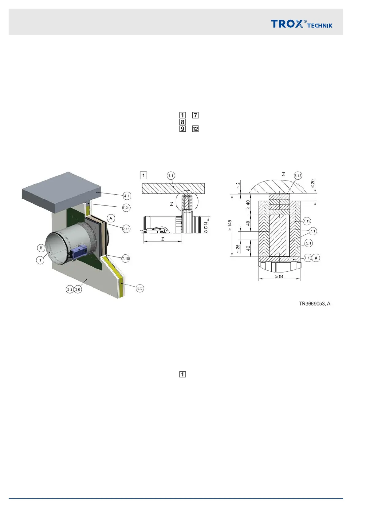
Dry mortarless installation into a lightweight partition wall, below a flexible ceiling joint with installation kit
TQ
Fig. 44: Dry mortarless installation into a lightweight partition wall, below a flexible ceiling joint with installation kit TQ
1 FKR-EU
2.11 Installation kit TQ (factory assembled)
3.2 Lightweight partition wall with metal support
structure, cladding on both sides
3.6 Compartment wall or safety wall with metal sup-
port structure, cladding on both sides
4.1 Solid ceiling slab
5.1 Dry wall screw
6.5 Mineral wool (depending on wall construction)
6.13 Mineral wool strips A1, ≤ 5 mm thick, ≤ 1000°C,
filler as an alternative
7.1 UW section
7.10 Trim panels
7.13 Cladding
7.21 Ceiling joint strips (e.g. 4 × ≥ 10 mm)
Z Spigot construction 370 mm
Flange construction 342 mm
# Depending on the wall structure
Up to EI 90 S
Note: representative illustration. The distance to the ceiling depends on the design of the flexible ceiling joint, the
expected ceiling subsidence and the specifications of the wall manufacturer.
Additional requirements: dry mortarless installation
with installation kit TQ in lightweight partition walls
Lightweight partition wall or compartment wall,
Ä
on page 34
Installation kit TQ,
Ä
on page 32
≥ 200 mm distance between two fire dampers in
separate installation openings
Fasten the cover plate with 4 (for nominal widths up
to 400 mm) or 12 (for nominal widths from 450 mm)
dry wall screws Æ ≥ 4.2 mm to the metal support
structure
Installation
Lightweight partition walls > Dry mortarless installation with installation ...
Fire damper FKR-EU64