Service Procedures
12
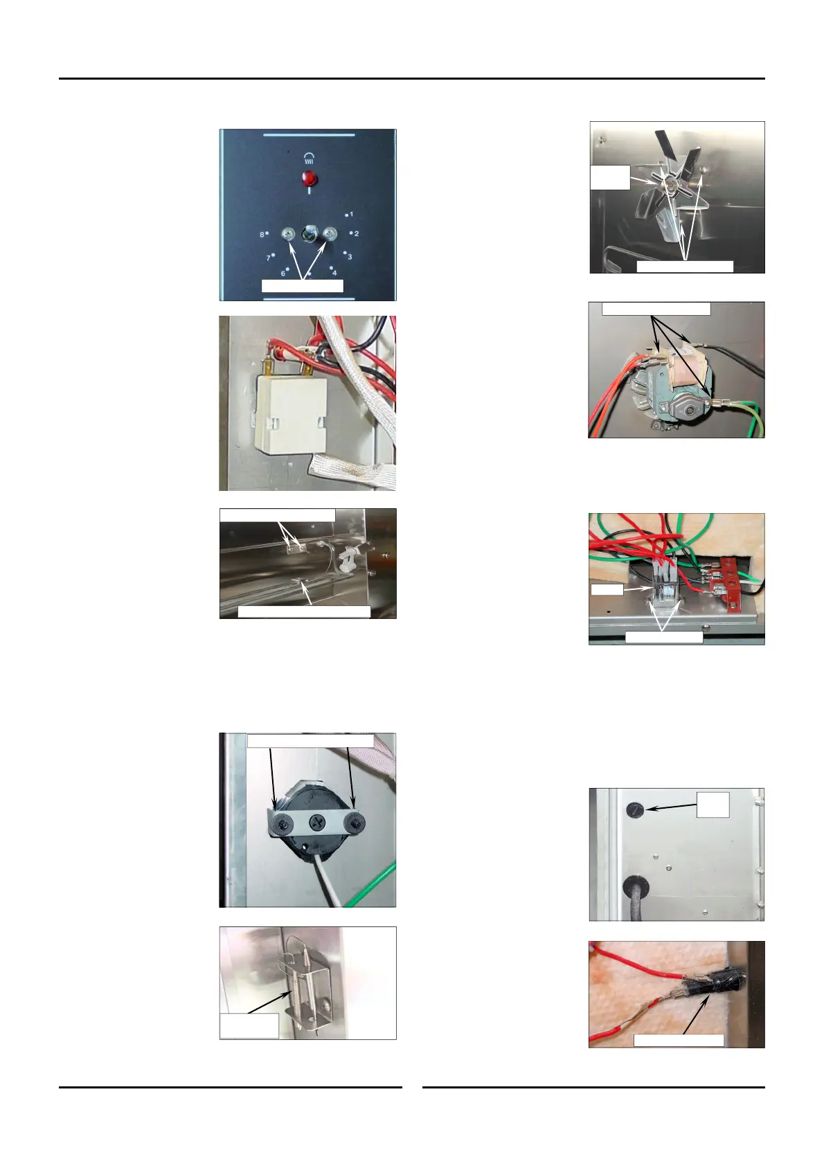
5.2.3 Humidity Control Thermostat
1. Remove knob from
switch spindle. Knob is
a push fit.
2. Remove control panel
(Refer Section 5.1.1).
3. Remove 2 switch
mounting screws and
remove switch from
rear of control panel.
4. Remove RH Side Rack
from oven. (refer
Section 5.1.3).
5. Remove Fan Baffle.
(refer Section 5.1.4).
6. Remove RH access
panel (refer Section
5.1.2).
7. Disconnect wires from
rear of Humidity
Control Thermostat,
noting their position.
8. Undo 2 screws and
remove plate in
proofer / holding
cabinet RH side wall.
9. Remove humidity
control phial from
water element clamp.
10. Withdraw humidity
control phial through
proofer / holding
cabinet side wall.
11. Re-assemble in reverse
order.
5.2.4 Thermometer
1. Remove control panel
(Refer Section 5.1.1).
2. On rear of control
panel, undoing thumb-
screws and remove
bracket and
thermometer.
3. Remove RH Side Rack
from proofer. (refer
Section 5.1.3).
4. Remove Fan Baffle.
(refer Section 5.1.4).
5. Remove RH access
panel (refer Section
5.1.2).
6. Remove phial from
holder inside proofer.
7. Withdraw phial through
proofer / holding
cabinet sidewall.
8. Re-assemble in reverse
order.
Securing Screws
Humidity
Control Phial
Humidity Control Phial Clamp
Remove Screws and Plate
Remove Screws and Bracket
5.2.5 Fan Motor
1. Remove RH Side Access
Panel from proofer /
holding cabinet. (refer
Section 5.1.2).
2. Remove RH Side Rack
from oven. (refer
Section 5.1.3).
3. Remove Fan Baffle.
(refer Section 5.1.4).
4. Undo securing nut and
remove fan blade.
5. Disconnect wires from
fan motor.
6. From inside proofer,
undo fan mounting
screws.
7. Remove motor from
proofer.
8. Re-assemble in reverse
order.
5.2.6 Relay
1. Remove RH access
panel (refer Section
5.1.2).
2.
Disconnect wires from
relay (note positions).
3. Remove 2 securing
screws and remove
relay.
4. Re-assemble in reverse
order.
5.2.7 Fuse and Fuse Holder
The fuse holder is located on rear panel, just above power
entry point. To access fuse, unscrew centre of holder and
withdraw fuse.
1. Remove RH access
panel (refer Section
5.1.2).
2. Disconnect connections
from rear of fuse
holder.
3. Push fuse holder out of
rear panel.
4. Re-assemble in reverse
order.
Securing
Nut
Fan Mounting Screws
Disconnect Connections
Securing Screws
Relay
Fuse
Holder
Rear of Fuse Holder

 Loading...