Service Procedures
15
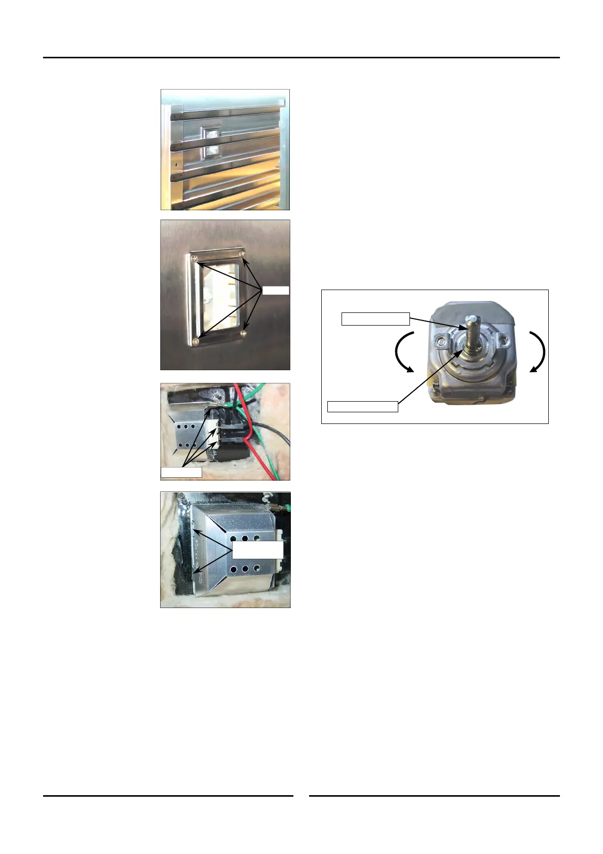
5.3 Adjustment & Calibration
5.3.1 Temperature Calibration
1. Remove thermostat control switch (refer 5.2.2).
2. Adjust calibration collar located at base of thermostat
shaft.
3. Adjustment of calibration collar by 1° angular will alter
Proofer temperature by approximately 2°C (36°F).
4. To increase temperature, turn thermostat shaft fully
counter-clockwise then turn calibration collar, counter-
clockwise.
5. To decrease temperature, turn thermostat shaft fully
clockwise then turn calibration collar clockwise.
6. Refit thermostat control switch.
7. Turn On power and re-check thermostat calibration.
Thermostat Shaft
Calibration Collar
+
-
5.2.12 Lamp Assy
1. Remove LH access
panel (refer Section
5.1.2).
2. Remove LH Side Rack
from proofer.
(refer
Section 5.1.3).
3. Remove 4 screws
securing support frame.
4. Remove support frame,
glass lens and gasket.
5. Remove light bulb if
required (this is a push
fit into housing).
6. Pull back insulation to
reveal rear of lamp
assy.
7. Disconnect electrical
connections on rear of
lamp assy.
8. Depress spring loaded
locking tabs on rear of
light assy. Push light
assy into proofer and
remove from proofer.
9. Re-assemble in reverse
order.
Screws
Disconnect
Depress Spring
Tabs

 Loading...