Service Procedures
14
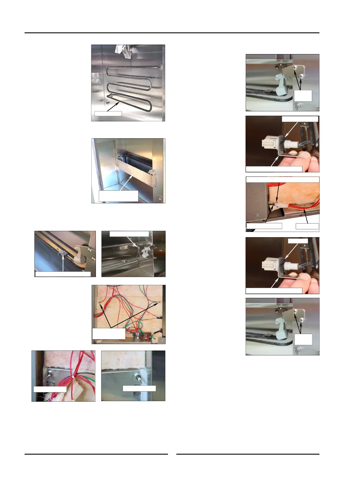
5.2.11 Float Switch
1. Remove Control Panel.
(refer Section 5.1.1).
2. Remove RH Side Rack
from proofer. (refer
Section 5.1.3).
3. Remove Fan Baffle.
(refer Section 5.1.4).
4.
Lift out and remove the
water trough.
5. Remove 2 screws
securing float switch
bracket to prover.
6. Unscrew locknut
securing float switch to
mounting bracket.
7. Remove RH access
panel (refer Section
5.1.2).
8. Disconnect float switch
plug at connector.
9. Cut off plug from float
switch end of cable.
10. Pull cable through hole
into prover.
11. Remove float switch
mounting bracket and
lock nut from cable.
12. Fit float switch mount
bracket and lock nut
onto new float switch
cable, ensuring bracket
is orientated correctly
and tighten up locknut.
13. From inside prover,
feed cable through hole
in prover side wall and
out to RH side of oven.
14. Fit supplied 2 Way Cap
to terminal ends of float
switch cable and
connect up plug to
connector from relay.
15. Refit float switch
mounting bracket and
secure with 2 screws.
16. Refit water trough and
check float switch operates in a vertical movement
without catching the sides of the water trough.
17. Refit Control Panel. (refer Section 5.1.1).
18. Refit RH Side Rack. (refer Section 5.1.3).
19. Refit Fan Baffle. (refer Section 5.1.4).
20. Refit RH access panel (refer Section 5.1.2).
4. Remove RH Side Rack
from proofer. (refer
Section 5.1.3).
5. Remove Fan Baffle.
(refer Section 5.1.4).
6. Withdraw dry element
from inside proofer /
holding cabinet.
7. Re-assemble in reverse
order.
5.2.10 Wet Element
1. Remove RH Side Rack
from proofer. (refer
Section 5.1.3).
2. Remove Fan Baffle.
(refer Section 5.1.4).
3.
Lift out and remove the
water trough.
4. Unscrew and remove
humidity control phial
from element by
loosening and removing
clamp. Remove phial
from element.
5. Remove RH access
panel (refer Section
5.1.2).
6. Disconnect electrical
connections to the dry
element.
7. Pull back insulation to
reveal terminals.
Unscrew locking nuts.
8. From inside the proofer,
withdraw the element.
9. Re-assemble in reverse
order.
Dry Element
Remove Clamp here
Lift Up and Remove
Water Trough
Humidity Control Phial Clamp
Disconnect Elect
Connections
L/Hand Terminal
R/Hand Terminal
Securing
Screws
Unscrew Lock Nut
Disconnect and cut off this end of Plug
Float Switch Mounting Bracket
Lock Nut
Float Switch Mounting Bracket
Securing
Screws
From Float Switch
From Relay
 Loading...
