5
Installation 2
Amendment 10
11 May 2015
Location
1. This oven must be installed in an area of adequate air supply.
Adequate ven
tilation is essential, to prevent dangerous buil
d
up
of combustion products. DO NOT obstruct the
air flow
around
the ventilation slots.
2. This oven must be fitted on supplied legs in all installations.
(When installed on a manufacturers stand, the le
gs are used
to l
ocate the oven in the correct position.
3. All air for burner combustion is supplied from beneat
h the
appl
iance. Legs must always be fitted and no obstructions
placed beneath or around the base of the applianc
e, as
ob
structions will cause incorrect operation and / or failure
of
the ap
plianc
e.
4
. Installation must allow for a sufficient flow of fresh
air for the
c
ombustion air supply.
5.
The area around the appliance must be kept free and cl
ear
from comb
ustibles.
6. Position the oven in its approximate working positi
on.
It
should be positioned so that the control panel and ov
en
shelve
s are easily reachable for loading and unloadi
ng.
7
. Use a spirit level to ensure oven is level from side to si
de and
fron
t to back. (If this is not carried out, uneven cooking could
occur).
Clearances
1. To ensure correct ventilation for the motor and controller, the
fol
lowing minimum installation clearances are to be adhered
to:
CLEARANCE FR
OM SOURCE OF HEAT.
A minimum distance of 300mm (12”) from appliance sides
is required.
NOTE: Fixed installations require at least 500mm clearance
at the right hand side of oven for service access.
Oven Vent
Important:
The vent located on the top of the oven must NOT be
obstructed.
Electrical Connection
Eac
h oven should be connected to an adequately protected power
supply and an isolation switch mounted adjacent to, but not
behind the oven and must be readily accessible to the operator.
This switch must be clearly marked and readily accessible in case
of fire.
Check the electricity supply is correct to as shown on the
Technical Data Plate on the front right hand corner of the oven
side panel.
Ensure that the oven is fitted with the appropriate power cord and
plug.
Gas Connection
A ½" BSP or ½" N.P.T connection is provided at the bottom rear
of the oven.
A restraint chain anchor has been provided below the gas
connection point on the appliance, for fitment of a restraint chain.
It is important that adequately sized piping run directly to the
connection joint on the oven with as few tees and elbows as
possible to give maximum supply volume.
A suitable jointing compound which resists the break down action
of LPG must be used on every gas connection.
Check all gas connections for leakages using soapy water or other
gas detecting equipment.
Check the technical data plate located on the front right hand
corner of the oven, for correct operating pressure and gas orifice
size for the gas being used, before operation.
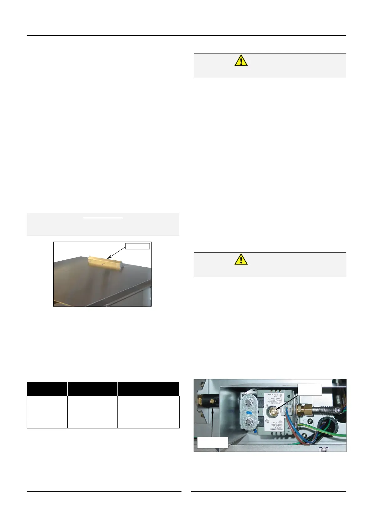
The appliance combination gas valve is fitted with an internal
regulator for adjusting the operating pressure. To access, remove
appropriately marked service panel from beneath the oven door.
Unscrew and remove regulator cap from the gas valve. Adjust the
regulator to achieve the stated pressure. Also refer to the
‘Specifications’ section.
NOTE: The Pressure Test Point is located behind the front
service panel beneath the oven door.
Thi
s oven must be earthed / grounded.
Warning
Do not
use a naked flame to check for gas leakages.
Warning
Regulator
Cap
Pressure Test
Point
Combustible
Surface
Non Combustible
Surface
Left / Right
Hand Side
75mm/3” 75mm/3”
Rear 75mm/3” 75mm/3”
Top 600mm/24” 200mm/8”
 Loading...
