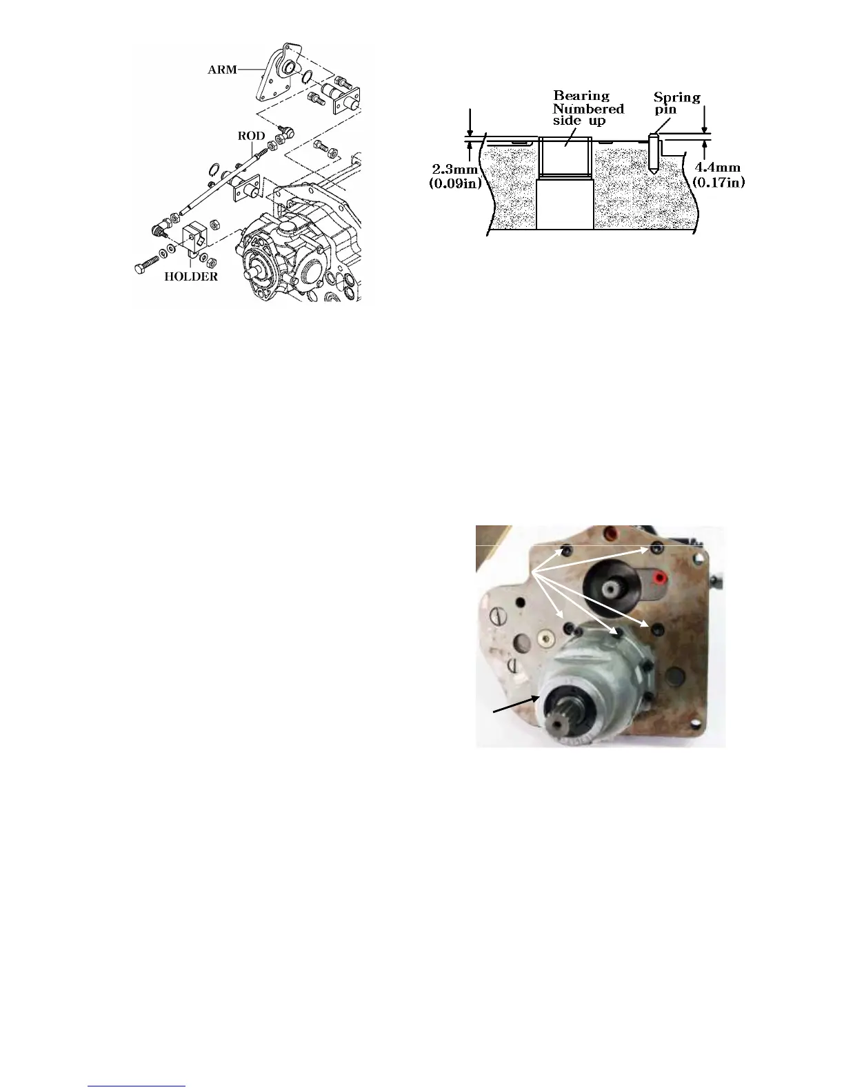
NOTE: If neutral adjustment cap screw is
loosened,neutral adjustment procedure must be
performed.see “HYDRAULIC PEDAL AND
NEUTRAL ADJUSTMENT”
15.Inspect pivot and cam followers on neutral
return lever for smooth operation.Replace
parts as needed.
Back plate Assembly:
1.On motor side of the back plate,install the
filter bypass valve.Tighten to 16-20N.m
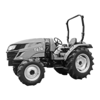
8. If the bearings were removed from the back
plate,press new ones into position using a
suitable bearing driver.The numbers on the
bearing should face the outside of the back
plate.press the bearing in until 2.3±0.2 mm
(0.09in ±0.010in) of the race remains
above the surface of the back plate.
9. If removed,install the spring pin that is used
to position the valve plate.Allow the pin to
protrude from the back plate approximately
4.4mm(0.17in).
4. HYDRAULIC PUMP
DISASSEMBLY
NOTE:Cooler bypass valve spring and charge
relief valve spring could accidentally be mixed
up.Charge relief valve spring is thicker.
2.Install the cooler bypass valve.Tighten to
28-33 N.M(21-24 lb-ft).
IMPORTANT: Old O-rings,gaskets and seals
will leak.Always install new O-rings,
gaskets and seals during assembly.
3.Install new O-ring to plug.Install plug.
Tighten to 13-16N.m(115-142lb-in)
4.On pump side of back plate,install new
O-ring to the three plugs.Install plugs.
Tighten to 135-149N.m(100-110 lb-in).
5.Install forward and reverse relief valves in
ports marked at disassembly.Tighten to
135-149N.m(100-110lb-ft).
6. Install charge pressure relief valve.Tighten
to 37-41N.m(27-30lb-ft).
7.Install two dowel pins.
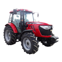
IMPORTANT: The pump body is aluminum
and can be easily damaged by steel tools.
Be careful to not damage machined surfaces.
Do not use screw driver or other sharp
objects to pry pump body from back plate.
1.If not already done,remove four socket head
cap screws securing the pump to the back
plate .Tap pump body with a plastic mallet to
remove pump.
4-26
Cap screws
Hydrostatic
motor