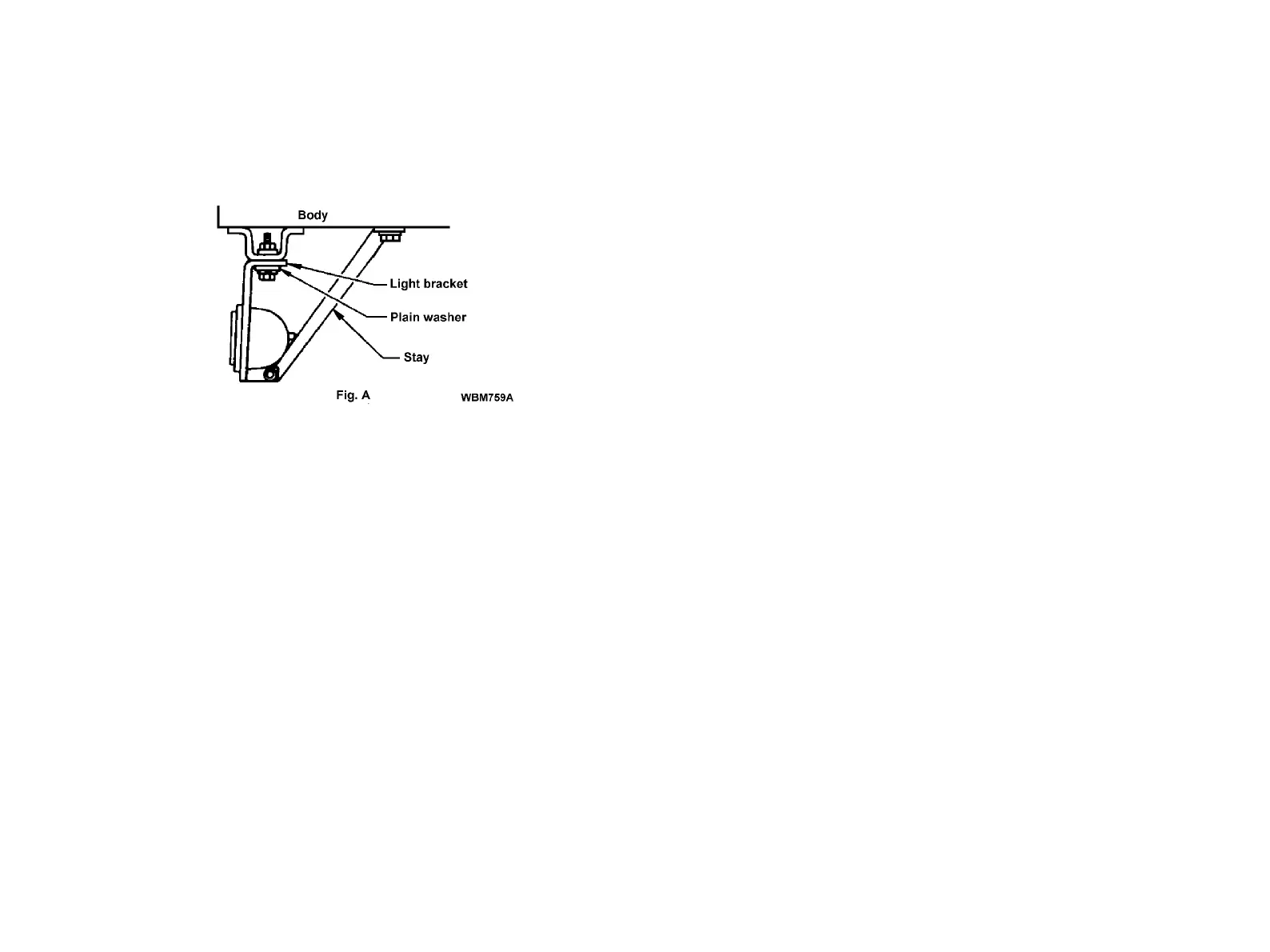
• Installation using upper fitting holes-
Tighten the light bracket with 0.31 in (8 mm) diameter hexagonal bolts
and nuts at 3 places. Be sure to use plain washers. Support the light
with a stay to avoid the light vibration.
(b) The license plate light and holder assembly is bolted on the rear frame
crossmember. If it is not necessary to relocate this assembly, replace
the bolts and nuts with rivets, or weld each nut and bolt assembly to
prevent loosening. If the light is moved, care must be taken not to
change the relative position between the holder and the light. Assure
that the assembly is permanently affixed.
5. ADDITION OF OTHER LIGHTS AND ELECTRICAL COM-
PONENTS
When the total wattage of the lights on Table III of paragraph 4
exceeds 108 watts, or when adding a light other than one described in
paragraph 4 and other electrical components, install the wiring circuit
according to paragraph 3 and the instructions below.
(1) Power supply (12-bolt)
• The fuse box located inside the cab has a spare 15A power source.
When adding a circuit, use SAE Type 1A 1/4 terminal (see SAE
J858a) for the connection terminal and an automotive low-tension wire
AWG16, (1.25 mm
2
). Properly insulate the connections.
• The load current should be less than 10A (120 watts).
• When connecting a load of more than 10A (120 watts), take power
from the vehicle’s junction block or a point as close to the battery as
possible. Be sure to install a fusible link, fuse or circuit breaker for cir
-
cuit protection.
(2) Switch for added device
• When controlling an added light with an existing switch, install a relay
for the light. Be careful to pass only the actuating current for the relay
through the switch. The load current for the added light must not be
passed through the switch.
Other added loads must not be controlled by existing switches. Be
sure to install an exclusive switch for each added device. When add-
ing switches inside the cab, extra care must be used to prevent inter-
ference to existing wiring.
C23
 Loading...