3. PRECAUTIONS FOR PERFORMING WORK OPERATIONS
a When removing or replacing parts on standard vehicles, follow the
procedures described in the Service manual.
b When mounting additional equipment or welding, be very careful to
avoid damage to nearby parts.
c When mounting additional equipment, make sure that all wheels are
on level surface so the chassis frame does not warp.
4. POINTS TO CHECK AFTER MODIFICATIONS HAVE BEEN
COMPLETED
a Make sure that inspection, maintenance and adjustment operations
for standard vehicle parts will not be hindered. When modifications
create changes in work procedures write an explanation and include
it with the vehicle.
b Write an explanation for operation and inspection/repair procedures
for any additional equipment and include it with the vehicle.
c Remember to be responsible for the after-sales service of additional
equipment.
CHASSIS FRAME MODIFICATIONS
The chassis frame has been carefully designed to be well-balanced.
The installation of additional equipment may have a great effect upon the
frame. Drilling holes or welding may also adversely affect the balance.
Careless alterations may even damage the frame beyond repair. When
making such alterations, proceed with extreme caution.
When installing additional equipment, use existing holes and brackets
whenever possible. When drilling or welding is unavoidable, the following
precautions should be observed.
1. DRILLING HOLES IN THE CHASSIS FRAME
a Always use a drill to drill holes. Do not use gas torches or other heat
devices (gas, etc.) to create the holes.
b Smooth and finish holes after drilling.
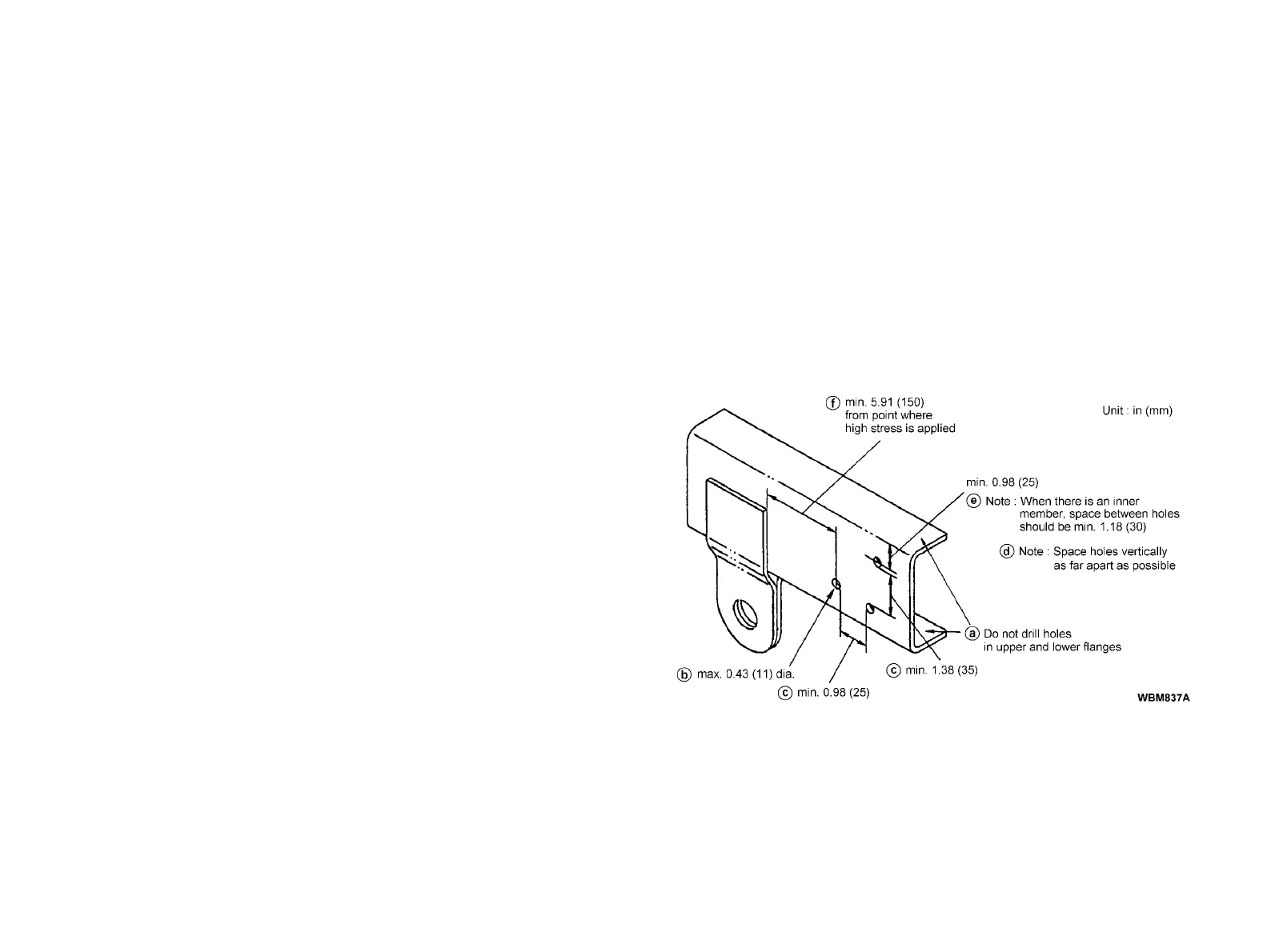
1) DRILLING HOLES IN THE CHASSIS FRAME SIDE RAIL
a Do not drill holes or create notches in the upper and lower flanges.
b Holes should be no more than 0.43 in (11 mm) in diameter.
c There should be at least 0.98 in (25 mm) of horizontal distance
between holes and at least 1.38 in (35 mm) vertical distance.
d Whenever possible, avoid drilling holes spaced vertically, as this
greatly affects frame strength.
e When drilling holes in ]-shaped parts, the distance from the upper or
lower flange to the center of the hole should be at least 0.98 in (25
mm). For parts that have an inner member, this distance should be
at least 1.18 in (30 mm).
f Holes should be at least 5.91 in (150 mm) from spring brackets and
other parts of great stress.
C8