NOTE : 1. It is the control to recover the DPF function by automatically
or forcibly burning the soot deposit in DPF. (The idle-up and
exhaust brake is operated during DPF control when the
vehicle is stopped.)
2. When the idle status continues for a set time, it is automat-
ically operated whether the PTO switch is turned ON or
OFF. (The idle-up and exhaust brake is operated when the
idle control is turned on.)
3. An engine speed is selected between the speed controlled
with the accelerator and the speed controlled with the
accelerator for operation (external engine control lever),
whichever is higher (Max speed).
2. Functions of junctions A and B
1) If installing the PTO switch (connected to junction A)
• The characteristic can be switched to All speeds by turning on the
PTO switch.
• A throttle opening is selected between the accelerator pedal and the
accelerator for operation (external engine control lever), whichever
is higher (Max value).
• The DPF recovery control is not operated when the PTO switch is
turned on.
2) If junction B is connected
• For vehicles without PTO switch the engine speed can be controlled
with the external engine control lever.
3) If both junction A (without PTO switch) and B are not connected.
• If the PTO switch is turned on, operations can be performed while
keeping the governor characteristic in the driving mode.
• The engine speed can be controlled with the accelerator pedal, but
it cannot be controlled with the engine control lever.
Cautions :
• Do not connect junction A and junction B at the same time.
• When installing the PTO switch (connected to junction A),
always turn off the PTO switch before driving. Failure to turn
off the PTO switch will cause the governor characteristic to
remain at All Speeds, so if is very dangerous.
• The adjusting bolt of the external engine control lever is already
set before shipping. Do not adjust it.
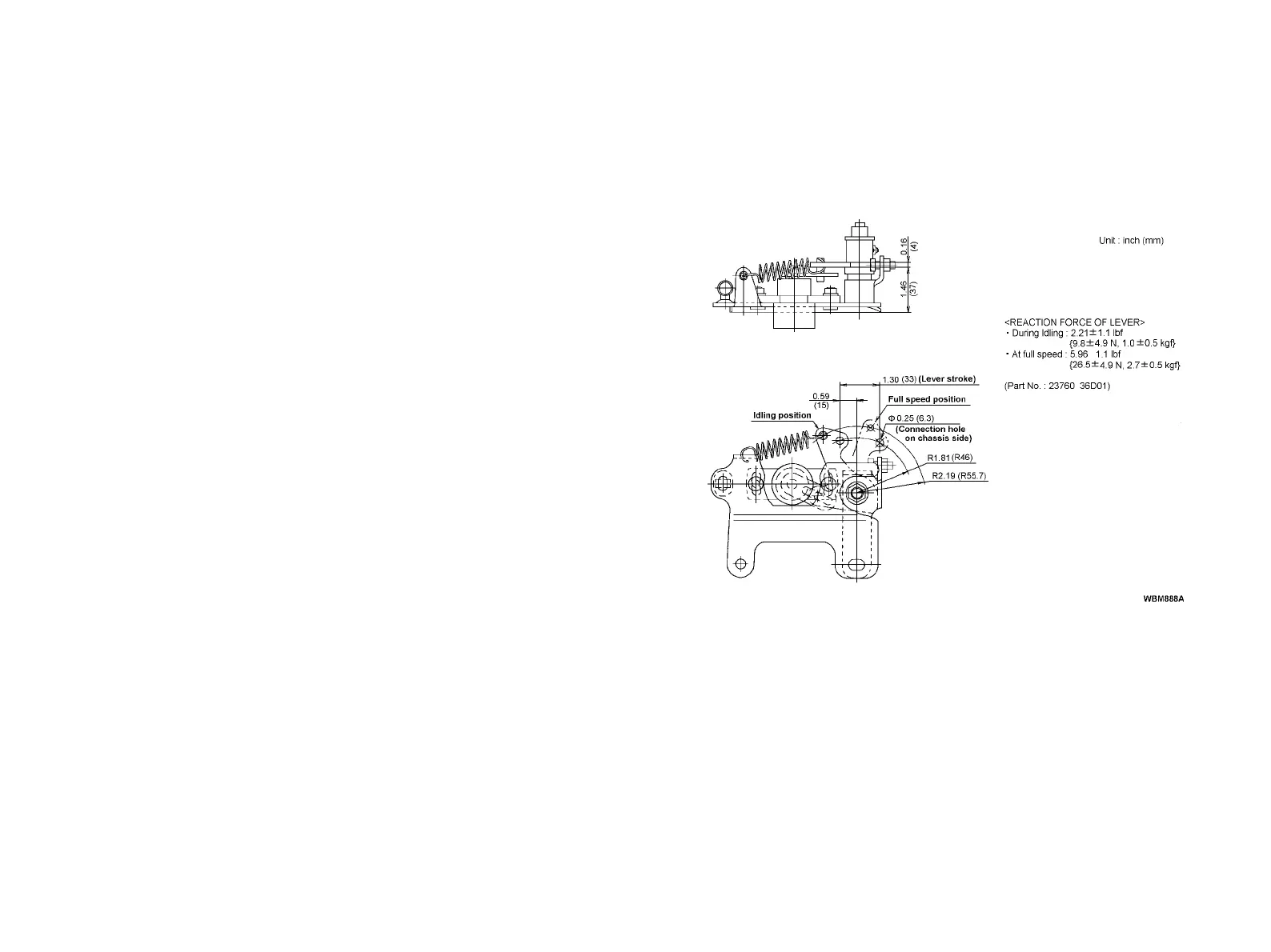
3. Engine control lever
4. Attachment
1) Attach the engine control lever on the chassis side.
When connecting to the linkage on the chassis side, take the
following precautions.
NOTE :
• Set the engine control lever with adequate play leftover so
that it can return to the idling position without fail during
driving (idling).
• To prevent deformation when the engine is running at full
speed, leave a clearance of 0.04 inch (1 mm) between the
engine control lever and the adjusting bolt on the full speed
C24