ENKOFORM VMK
Construcción
36
ENKOFORM VMK
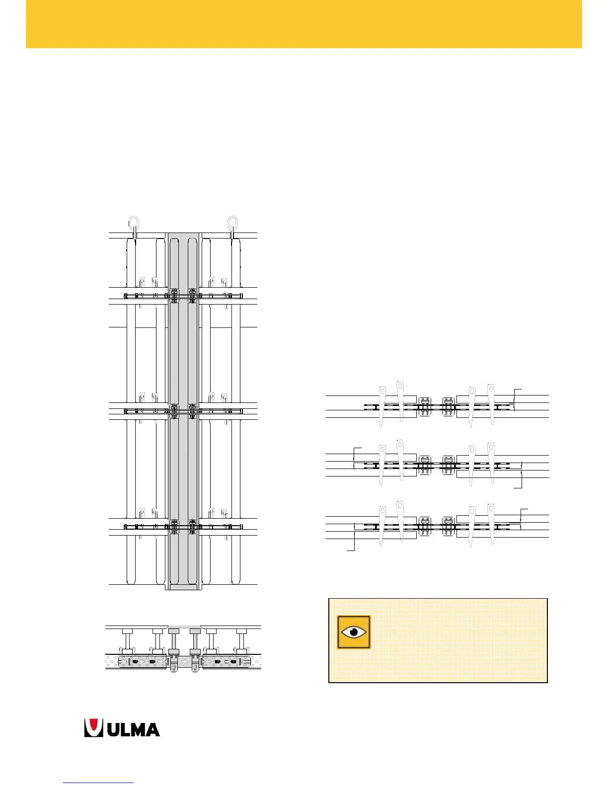
4.5.1.1 Making filler panels
FILLER PANELS are formed by ADJUSTABLE
CONNECTOR MK, WALER-VM20 CLAMPS, VM20
BEAMS and BOARD.
FILLER PANELS will have the corners of the BOARD cut
in chamfer (on both sides).
Both PANELS will also have corners cut in chamfer.
This allows an easier stripping.
FILLER PANEL between 2 PANELS.
Detail of the FILLER PANEL.
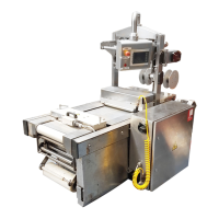
4.5.1.2 Correction of the assembling errors of
the walers in panels
Some errors could be made when assembling
PANELS (for example, misplacing the WALER MK-
120 in height). Therefore, when 2 of these PANELS
were placed next to each other, their MK-120
WALERS would not match in height, and it would
bring problems to join the two PANELS.
The gap between the width of the ADJUSTABLE
CONNECTOR MK and the hollow of the WALER MK-
120 allows an 1,1 cm error tolerance.
The PANEL CONNECTOR is designed in such a way
that whenever it works in this range, the
CONNECTOR will work in a proper way. If the
assembling error is bigger, it will not be possible to
introduce the PANEL CONNECTOR in the joint.
Error range of assembly that absorbs the ADJUSTABLE
CONNECTOR MK.
11
11
11
11
11
The gap between the width of the
ADJUSTABLE CONNECTOR MK and the
hollow of the WALER MK-120 allows an
1,1 cm error tolerance.